If the R to ground off the + input of the opamp (which this feeds) is 50Kohm or higher, this filter will be pretty effective. It would be more effective if this 50K was 1Mohm, but then you've got a 1mohm R making hiss noise. I usually use 50K there and believe it to be a good tradeoff.
Agree with most of what you write for line level, but for this para. The R off the ground to the + input in an AC coupled input stage is there to source or sink the bias current and set a reference level. Input thermal noise level is determined by source impedance, 2 K in the example you used.
This R will generate excess noise however, so for high bias current, R can 't be too high. This is one of the locations where a good quality resistor can be important.
Last edited:
If the input is loaded with Noise producing 1M resistor alone, then we can call the stage noisy.
If the 1M resistor is not alone and we have a pair of parallel resistors say 1k||1M then the amplifier sees an effective 999r as the "noise producer".
Most would not call that a noisy stage.
If we wanted a very quiet stage we could leave the 1M in place and replace the 1k with 10r.
The effective "noise producer" is now 9r9999.
I think everyone would agree that the noise added to this stage is very low and that the 1M has NOT given rise to excess noise !
If the input is loaded with Noise producing 1M resistor alone, then we can call the stage noisy.
If the 1M resistor is not alone and we have a pair of parallel resistors say 1k||1M then the amplifier sees an effective 999r as the "noise producer".
Most would not call that a noisy stage.
If we wanted a very quiet stage we could leave the 1M in place and replace the 1k with 10r.
The effective "noise producer" is now 9r9999.
I think everyone would agree that the noise added to this stage is very low and that the 1M has NOT given rise to excess noise !
Yes, the bias current through the resistor produces excess noise, so don't use a large value carbon composite in this location, for example. For the rest your sums are correct.
Thanks for the correction about the 1M noise source being shunted by the source impedance. I wasn't sure about that. The reason I pick 1K rather than 10R for the series R is because the source impedance (DVD or CD player or Tuner ?) may be unknown or may vary when you select different inputs. A 1K largely swamps that out in 98% of the cases and gives you pretty good consistency. I always use 1% metal film resistors unless I'm needing high power resistors in an output stage or power supply. Carbon film's only positive feature is that they blow open easier if that's a feature.

Noise from a carbon resistor can hide higher harmonics.
I call it analog dither.
That may make the sound somewhat rounder and softer.
In a strict sense this is not HiFi and i can remember that Levinson was very proud in the 70th to use metal film resistors.
Bulk foil and wire wound is even lower noise, excess noise, that is.
I call it analog dither.
That may make the sound somewhat rounder and softer.
In a strict sense this is not HiFi and i can remember that Levinson was very proud in the 70th to use metal film resistors.
Bulk foil and wire wound is even lower noise, excess noise, that is.
Rolling off the frequency response using a cap across the feedback resistor depends on the opamps ability to cleanly operate well above the frequency you want the rolloff at. But the feedback itself is rolling off as you go up in frequency, so by the time you get up to several hundred kHZ, because the feedback has become small, the opamp may not be very distortion free, so it acts like an AM radio detector and generates sum and difference frequencies based on whatever Rf energy is coming in. The feedback necessarily rolls off (even without the cap added) because you need a "dominant pole" well ahead of any other rollofff poles in order to have good phase margin. A dominant pole appears to be designed into all opamps. Look at the open loop F response graph.
So a much better way to dump Rf energy coming in is with a passive Rf filter ahead of the opamp circuit, which is just an R in series and a cap to ground. A true nerd might also put ferrite beads on the incoming wire so then it's an inductor in series and a cap to ground. A 2 pole filter instead of one pole. I don't bother with the beads (maybe I should).
To design this filter you need to have some idea what the source impedance will be. If your source takes a signal from the plate of a tube, you can be way off on this, but virtually all other sources I know of will have an output impedance of less than 1kohm, so I design for that. Since series resistors can add hiss noise I prefer to keep the series resistor small. I usually go with 1k, which adds to the 1K source impedance from the point of view of the cap to ground after the R. So then you just calculate a cap based on 2kohms. Whatever input impedance to ground resistance the opamp circuit will have will create a "zero", which cancels the rolloff, so you want that to be as high as is practical. For a one pole RC passive filter the math is:
C = 1/ (2 times pie times F times R as seen by the cap)
Example: C = 1/ (6.283 x 100kHZ x 2kohms) = 796pF
So then you choose the nearest standard value which in this case is either 820pF (rare but I think they exist) or 1nF (very common).
If you choose 1nF, the actual -3dB point will be :
F = 1/ (2 pie x 1nF x 2Kohm) = 80kHZ
If the R to ground off the + input of the opamp (which this feeds) is 50Kohm or higher, this filter will be pretty effective. It would be more effective if this 50K was 1Mohm, but then you've got a 1mohm R making hiss noise. I usually use 50K there and believe it to be a good tradeoff.
This Rf filter is for signals coming into the chassis. I don't put one of these on each stage within a given chassis.
A series R at the final output of a preamp circuit, for example (usually 100 - 200 ohms) will make the opamp more stable (very important), and also form an RLC filter with the interconnect cable that goes to the poweramps, so it's good to be aware of how much capacitance that interconnect cable will have if it's very long. It will form another passive Rf filter itself.
Thanks for the information, it led to a very insightful discussion.
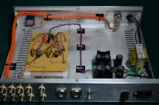
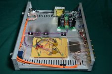
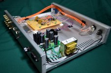
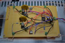
Here is the final product pictures, only measurement I took is of the output offset which is easily dialed to 0.0 VDC. I am sure it will drift a bit here and there as things warm up and cool down, but not by much at all. Maybe tomorrow I fire up the scope.
Attachments
Last edited:
Joachim,
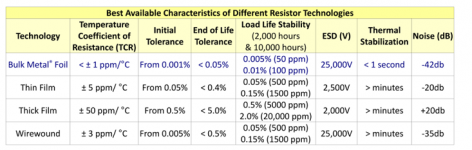
About the overview of different kinds of resistors - thanks for posting it - what do they mean by thermal stabilisation? Another thing I don't quite understand is the noise levels. Is this excess noise @ a certain current through a defined resistance? And how can noise be +20 dB? Against which standard? So many questions, so little time.
About the overview of different kinds of resistors - thanks for posting it - what do they mean by thermal stabilisation? Another thing I don't quite understand is the noise levels. Is this excess noise @ a certain current through a defined resistance? And how can noise be +20 dB? Against which standard? So many questions, so little time.
Don't use a carbon composition resistor unless the duty demands that ONLY carbon composition can do the job.
ultra low inductance, provided the size of the carbon comp does not increase the loop area too much.Do you have an example where carbon composite would be better than for example thin film?
Yes, metal films are spiraled so they have some inductance.
There is a way though to make low inductance metal film.
The bulk foils are low inductance too because of the etching pattern.
Wirewounds can also be made low inductance with bifilar winding.
I think the noise level is excess noise.
That is the extra noise above the Johnson noise.
I do not really understand that list too.
What is 0dB then ?
Thermal stabilization may be the time it needs from when you put voltage over the resistor until it reaches the nominal value.
This type is low inductance for example :http://www.vishay.com/docs/28769/mbasmahf.pdf
The range goes only to 470 Ohm though.
The range goes only to 470 Ohm though.
Whaleman, looks great except for the input wires all being bundled together. There may be substantial crosstalk when a non-selected input source is active. I recommend using shielded cables for each input wire, but only grounding the shield at one end. Then you should be able to bundle them without a crosstalk problem.
Whaleman, good to see your nice piece of work from the inside. Have you listened to it yet?
I am just starting to get some time in front of it. The attributes I've heard so far is that is quite revealing, very fast, lots of clarity and separation. I have heard some very low bass notes that I had not heard before, it has very good and wide frequency range. It does not glare in any area, but being very fast, loud transients can startle. I think it is a tad better than the 49720, but like Bob said, proper implementation is key. Specifically input impedance.
Whaleman, looks great except for the input wires all being bundled together. There may be substantial crosstalk when a non-selected input source is active. I recommend using shielded cables for each input wire, but only grounding the shield at one end. Then you should be able to bundle them without a crosstalk problem.
Those CAT6 plenum wires are "supposed" to be x-talk resistant. But I know I could do better with coax shielded type to prevent the x-talk that does still happen. I just like these too much and have a couple hundred feet spool. If you all turn me on to some small signal coax that does not cost too much, I may just switch.
Maybe tonight the pre sees the scope again.
Crosstalk will not be eliminated by twisting of pairs adjacent to each other.
The bigger the separation the higher the attenuation of crosstalk.
But infinite separation will not achieve zero crosstalk.
The switches will allow crosstalk.
Similarly for coax fed channels. Perfect coax will suffer switch crosstalk just as twisted pairs will.
The bigger the separation the higher the attenuation of crosstalk.
But infinite separation will not achieve zero crosstalk.
The switches will allow crosstalk.
Similarly for coax fed channels. Perfect coax will suffer switch crosstalk just as twisted pairs will.
This type is low inductance for example :http://www.vishay.com/docs/28769/mbasmahf.pdf
The range goes only to 470 Ohm though.
I think that low-inductance-designed resistors are largely unnecessary in higher values of resistance, since the small inductance of even conventionally-made resistors will have a very high corner frequency of the inductance and resistance, since that corner frequency is proportional to resistance.
I have also found that metal oxide film resistors in small values usually have quite small inductance, and that they tend to be better for use as emitter resistors in power amplifier output stages than wirewound resistors (certainly better than conventional wirewould). They are often handily available only up to 3 watts, so if RE needs to be bigger than 3 watts two or more need to be placed in parallel.
Cheers,
Bob
- Status
- This old topic is closed. If you want to reopen this topic, contact a moderator using the "Report Post" button.
- Home
- Amplifiers
- Solid State
- National opamp inflation