5.1 = 4 tpa3116? I think you need 120watt per 3116chip at 24V?
I would assume three tpa3116 chips in BTL mode (for the five channels), and one in PBTL mode (for the .1/sub).
We can back out needed power supply using the datasheet, specifically the graphs on pages 10 and 12.
For BTL at 24V, assuming 4 ohm speakers, 26 dB gain: max output power (10% TDH) is 75 Watts/channel, or 150 Watts for two channels. Efficiency at 75 Watt output is off the table, but 85% is probably a reasonably conservative estimate.
The power supply needs to supply about 177 Watts for the tpa3116 to output it's maximum of 75 WPCx2 at 85% efficiency. At 24 Volts, that's just under 7.5 amps.
With three tpa3116 chips going all-out, total power supply requirement is 177x3 = 531 Watts.
Now a similar calculation for the PBTL chip, assume 24 V PSU, 2 ohm sub driver, 26 dB gain: max output power (10% TDH) is 150 Watts (only one channel, so no need to multiply by 2). Efficiency again is about 85%, so the calculation works out the same as above, so add another 177 Watts.
Total would be 531+177 = 708 Watts. That's about 30 Amps at 24V.
Seems awful high, but I think that in reality, you're highly unlikely to push all four chips at their absolute max all the time.
At the risk of beating a dead horse: again on output filter LC values. ")
I've basically been looking at a few sources:
Note that for all these tools/calculations, since the tpa3116 operates in BTL mode, always divide speaker impedance in half. That's been mentioned before in this thread, as well as the "Match Your Output Filter" thread linked above.
Some questions:
Some interesting results from the Okawa RLC tool:
border="1"
|-
| Spkr Imp (ohms)
| R (ohms)
| L (H)
| C (F)
| fc (Hz)
| Q
| Damping
|-
| 10
| 5.5
| 10u
| 680n
| 61k
| 0.697
| 0.717
|-
| 8
| 4
| 10u
| 680n
| 61k
| 0.959
| 0.521
|-
| 6
| 3
| 10u
| 680n
| 61k
| 1.278
| 0.391
|-
| 4
| 2
| 10u
| 680n
| 61k
| 1.917
| 0.261
|-
| 8
| 4
| 22u
| 680n
| 41k
| 1.422
| 0.352
|-
| 6
| 3
| 22u
| 680n
| 41k
| 1.896
| 0.264
|-
| 4
| 2
| 22u
| 680n
| 41k
| 2.844
| 0.176
|-
| 8
| 4
| 10u
| 1250n
| 45k
| 0.707
| 0.707
|-
| 6
| 3
| 10u
| 1250n
| 45k
| 1.414
| 0.354
|-
| 8
| 4
| 4.7u
| 2200n
| 49k
| 0.365
| 1.368
|-
| 6
| 3
| 4.7u
| 2200n
| 49k
| 0.487
| 1.026
|-
| 4
| 2
| 4.7u
| 2200n
| 49k
| 0.731
| 0.684
Assuming I didn't make any transcription errors, is this table applicable? I literally just plugged in R, L, and C values to the tool, hit submit, and copied the resulting fc, Q, and Damping values.
As per my note above, I always set R to 1/2 speaker impedance (due to BTL operation of tpa3116).
IIRC, the stock YJBlue board has L=10uH and C=680nF---that's why the first few entries of the table use those values. Assuming a 61 kHz cutoff frequency is ok, it looks like stock YJBlue is best suited for a 10 ohm speaker?
I'm sure I'm missing something here, hence all the questions.
I've basically been looking at a few sources:
- Understanding output filters for Class-D amplifiers, EE Times, John Widder and Yun Tao Zhao, 1/9/2008
- RLC Low-pass Filter Design Tool, OKAWA Electric Design
- Match Your Output Filter to Your Speakers - All Boards Welcome, DIYAudio, jyoung070848, 31st January 2012
Note that for all these tools/calculations, since the tpa3116 operates in BTL mode, always divide speaker impedance in half. That's been mentioned before in this thread, as well as the "Match Your Output Filter" thread linked above.
Some questions:
- Is there an ideal cutoff frequency? Seems like I've seen 40ish kHz thrown around. Is this a rule-of-thumb value or a derived value?
- According to the EE Times article, an ideal Q factor is about 0.7. Is Q the parameter to try to optimize? In other words, is the right way to approach the LC filter design to start with speaker impedance, assume target Q=0.7, a cutoff frequency of 41000Hz (?), and find suitable L and C values?
- The EE Times article gives the formula for Q as: Q = RLv(C/2L). They don't explain what the "v" is. Is that "v" a constant or some derived value? Though I was able to manually calculate Q values consistent with those produced by the Okawa tool using this formula: 1/R*sqrt(L/C) (source: Wikipedia Q Factor).
Some interesting results from the Okawa RLC tool:
|-
| Spkr Imp (ohms)
| R (ohms)
| L (H)
| C (F)
| fc (Hz)
| Q
| Damping
|-
| 10
| 5.5
| 10u
| 680n
| 61k
| 0.697
| 0.717
|-
| 8
| 4
| 10u
| 680n
| 61k
| 0.959
| 0.521
|-
| 6
| 3
| 10u
| 680n
| 61k
| 1.278
| 0.391
|-
| 4
| 2
| 10u
| 680n
| 61k
| 1.917
| 0.261
|-
| 8
| 4
| 22u
| 680n
| 41k
| 1.422
| 0.352
|-
| 6
| 3
| 22u
| 680n
| 41k
| 1.896
| 0.264
|-
| 4
| 2
| 22u
| 680n
| 41k
| 2.844
| 0.176
|-
| 8
| 4
| 10u
| 1250n
| 45k
| 0.707
| 0.707
|-
| 6
| 3
| 10u
| 1250n
| 45k
| 1.414
| 0.354
|-
| 8
| 4
| 4.7u
| 2200n
| 49k
| 0.365
| 1.368
|-
| 6
| 3
| 4.7u
| 2200n
| 49k
| 0.487
| 1.026
|-
| 4
| 2
| 4.7u
| 2200n
| 49k
| 0.731
| 0.684
Assuming I didn't make any transcription errors, is this table applicable? I literally just plugged in R, L, and C values to the tool, hit submit, and copied the resulting fc, Q, and Damping values.
As per my note above, I always set R to 1/2 speaker impedance (due to BTL operation of tpa3116).
IIRC, the stock YJBlue board has L=10uH and C=680nF---that's why the first few entries of the table use those values. Assuming a 61 kHz cutoff frequency is ok, it looks like stock YJBlue is best suited for a 10 ohm speaker?
I'm sure I'm missing something here, hence all the questions.
Here's one more example, maybe simplifies things:
Using Okawa RLC Design Tool, I input R=8, L=22u, C=0.68u. Results:
Cut-off frequency, fc = 41148.5309373[Hz]
Quality factor, Q = 0.710995573743
Damping ratio, ζ = 0.703239258393
Now, I found this document: TI Application Report: Class-D LC Filter Design (referred to in this thread as "SLOA119A")
Bottom of page 4 has formulas for C and L:
C = 1 / ( fc_rad * R_L * sqrt(2) )
R = R_L * sqrt(2) / fc_rad
Where R_L = speaker impedance, fc_rad = cutoff frequency in radians/sec (little omega, i.e. cutoff freq in hertz * 2pi).
If input everything the same as the Okawa tool, except using R_L=4 (half of 8 above), then I get the exact same results.
Either one of these things is off by a factor of two, or (more likely), my application of dividing by two is wrong.
Using Okawa RLC Design Tool, I input R=8, L=22u, C=0.68u. Results:
Cut-off frequency, fc = 41148.5309373[Hz]
Quality factor, Q = 0.710995573743
Damping ratio, ζ = 0.703239258393
When I use the Okawa tool "Calculate the transfer function for RLC low-pass filter with R, L and C values" with input R=4 L=22u C=.68U
I get:
Cut-off frequency
fc = 41148.5309373[Hz]
Quality factor
Q = 0.703239258393
Damping ratio
ζ = 0.710995573743
Same or close to what you get for R=8. I am using this for an 8ohm impedance speaker and 1/2ing the impedance for R.
Confusing.
I did all those calculations at my work computer. Now I'm at home, and seeing your post, I assumed I did something wrong. But I just repeated it here, same result. Then I thought maybe it's a browser issue. But I got the same thing with Chrome, Firefox and IE.
What you are getting with R=4 is consistent with the TI application note document, as well as what all these PCBs are actually built with. I don't see how the tool would only be broken for "me", so maybe I'm using the wrong part of the website? Here's a screencap:

Edit: you used C=0.68u and my screencap shows 680n. I actually tried both, same result (as in reality 0.68uF = 680nF).
Last edited:
This is what I get for R=8 L=22u C=680n
Cut-off frequency
fc = 41148.5309373[Hz]
Quality factor
Q = 1.40647851679
Damping ratio
ζ = 0.355497786872
I agree, your results cannot be a one off, tried in Chrome and Firefox - same.
From this page RLC Low-Pass Filter Design Tool I use the section entitled "Calculate the transfer function for RLC low-pass filter with R, L and C values".
You can also download TI's very nice fully featured SPICE simulator program and just make the whole circuit including snubbers and your speaker load. Then calculate the transfer function for an AC input. Very nice for filter design. You can even select the 3116 as a circuit block and insert it.
I have used TINA to design and check filters, it is very good and easy to use.
SPICE-Based Analog Simulation Program - TINA-TI - TI Software Folder
I have used TINA to design and check filters, it is very good and easy to use.
SPICE-Based Analog Simulation Program - TINA-TI - TI Software Folder
I did all those calculations at my work computer. Now I'm at home, and seeing your post, I assumed I did something wrong. But I just repeated it here, same result. Then I thought maybe it's a browser issue. But I got the same thing with Chrome, Firefox and IE.
What you are getting with R=4 is consistent with the TI application note document, as well as what all these PCBs are actually built with. I don't see how the tool would only be broken for "me", so maybe I'm using the wrong part of the website? Here's a screencap:
View attachment 433246
Edit: you used C=0.68u and my screencap shows 680n. I actually tried both, same result (as in reality 0.68uF = 680nF).
Browse down to L-C-R filter where you see R like it is connected speaker. You filled in R-L-C filter, that is only difference. All values in table are wrong, seperate posted Q=.7 for 680n/22u 8 ohm is correct
I am new to DIY audio and just got a Yuan-Jing blue/black board. I just hooked it up and have a small question about hum/buzz.
I'm powering the amp with an 18V power brick plugged into a power jack connected to VCC/GND. And I have connected the speakers to the L+R outputs. When the amp is plugged in, there is a hum/buzz in the speakers. It goes away when an input source is plugged in, or when the inputs are shorted. It is present whether or not the 3-prong -> dual RCA input cable is plugged in -- whenever there is no input source it is there. Is this expected, or is there something I can do to reduce the hum/buzz when no input is plugged in?
I'm powering the amp with an 18V power brick plugged into a power jack connected to VCC/GND. And I have connected the speakers to the L+R outputs. When the amp is plugged in, there is a hum/buzz in the speakers. It goes away when an input source is plugged in, or when the inputs are shorted. It is present whether or not the 3-prong -> dual RCA input cable is plugged in -- whenever there is no input source it is there. Is this expected, or is there something I can do to reduce the hum/buzz when no input is plugged in?
Here are my new SER Coilcrafts. They are a thing to behold - huge and very beautifully made. I have never seen flat thick soiled wire like this. Will put them on my gen1 DUG amp next. I have both 22uH and 10uH, deciding which way to go - maybe 22uH for 8ohm speakers? I have been using 10uH and happy.
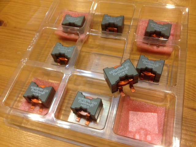
Attachments
You can also download TI's very nice fully featured SPICE simulator program and just make the whole circuit including snubbers and your speaker load. Then calculate the transfer function for an AC input. Very nice for filter design. You can even select the 3116 as a circuit block and insert it.
I have used TINA to design and check filters, it is very good and easy to use.
SPICE-Based Analog Simulation Program - TINA-TI - TI Software Folder
Here is the circuit:
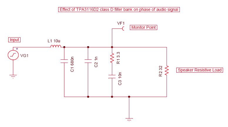
Here is the gain and phase of the above LC filter circuit for loads from 3.2ohms to 32ohms. It seems that the default 10uH and 680nF should work well for just about any speaker impedance as the gain variation is less than 1dB at 20kHz. The phase can be improved by using higher impedance speakers to reduce phase shift.

Based on the above result, I am going to use 10uH with 680nF for 8ohm speakers to reduce the phase shift. This helps me select whether or not to go 10uH or 22uH with my Coilcrafts.
Browse down to L-C-R filter where you see R like it is connected speaker. You filled in R-L-C filter, that is only difference. All values in table are wrong, seperate posted Q=.7 for 680n/22u 8 ohm is correct
Yup, that's it. Using the calculator for the wrong circuit. I knew I was doing something silly.
Now that I think I know what I'm doing (you be the judge), I hacked up a little script to generate the following table. I spot-checked some of the entries against the (appropriate) Okawa calculator. Except for some small rounding error, I think this is correct. For every speaker value, I did four calculations:[list="1]
[*] The theoretical ideal LC filter, with target cutoff frequency (fc) of 44.1kHz and Q=0.707
[*] The "closest" approximation of the theoretical using commonly available L/C values
[*] Cutoff frequency and Q values for fixed C=680nF and L=10uF (stock YJBlue board, other PCBs as well)
[*] Fixed C=680nF and L=22uF (stock Ybdz Wiener board, common mod mentioned here)
[/list]
Note: at least my version of TapaTalk doesn't render the table at all... just comes out as a jumble of numbers. Boo.
|-
| class="tcat" | SpkrImp
| class="tcat" | R_L
| class="tcat" | fc
| class="tcat" | C
| class="tcat" | L
| class="tcat" | Q
| class="tcat" | Damping
| class="tcat" | Notes
|-
| class="tcat" | Ohms
| class="tcat" | Ohms
| class="tcat" | Hz
| class="tcat" | F
| class="tcat" | H
|-
| 16
| 8.0
| 44.1k
| 319.0n
| 40.8u
| 0.707
| 0.707
| theoretical
|-
| 16
| 8.0
| 48.2k
| 330.0n
| 33.0u
| 0.800
| 0.625
| closest
|-
| 16
| 8.0
| 61.0k
| 680.0n
| 10.0u
| 2.086
| 0.240
| c=0.68uF/l=10uF
|-
| 16
| 8.0
| 41.1k
| 680.0n
| 22.0u
| 1.406
| 0.355
| c=0.68uF/l=22uF
|-
| 12
| 6.0
| 44.1k
| 425.3n
| 30.6u
| 0.707
| 0.707
| theoretical
|-
| 12
| 6.0
| 42.3k
| 430.0n
| 33.0u
| 0.685
| 0.730
| closest
|-
| 12
| 6.0
| 61.0k
| 680.0n
| 10.0u
| 1.565
| 0.320
| c=0.68uF/l=10uF
|-
| 12
| 6.0
| 41.1k
| 680.0n
| 22.0u
| 1.055
| 0.474
| c=0.68uF/l=22uF
|-
| 10
| 5.0
| 44.1k
| 510.4n
| 25.5u
| 0.707
| 0.707
| theoretical
|-
| 10
| 5.0
| 47.5k
| 510.0n
| 22.0u
| 0.761
| 0.657
| closest
|-
| 10
| 5.0
| 61.0k
| 680.0n
| 10.0u
| 1.304
| 0.383
| c=0.68uF/l=10uF
|-
| 10
| 5.0
| 41.1k
| 680.0n
| 22.0u
| 0.879
| 0.569
| c=0.68uF/l=22uF
|-
| 8
| 4.0
| 44.1k
| 638.0n
| 20.4u
| 0.707
| 0.707
| theoretical
|-
| 8
| 4.0
| 43.1k
| 620.0n
| 22.0u
| 0.671
| 0.745
| closest
|-
| 8
| 4.0
| 61.0k
| 680.0n
| 10.0u
| 1.043
| 0.479
| c=0.68uF/l=10uF
|-
| 8
| 4.0
| 41.1k
| 680.0n
| 22.0u
| 0.703
| 0.711
| c=0.68uF/l=22uF
|-
| 7
| 3.5
| 44.1k
| 729.1n
| 17.9u
| 0.707
| 0.707
| theoretical
|-
| 7
| 3.5
| 47.5k
| 750.0n
| 15.0u
| 0.783
| 0.639
| closest
|-
| 7
| 3.5
| 61.0k
| 680.0n
| 10.0u
| 0.913
| 0.548
| c=0.68uF/l=10uF
|-
| 7
| 3.5
| 41.1k
| 680.0n
| 22.0u
| 0.615
| 0.813
| c=0.68uF/l=22uF
|-
| 6
| 3.0
| 44.1k
| 850.6n
| 15.3u
| 0.707
| 0.707
| theoretical
|-
| 6
| 3.0
| 45.4k
| 820.0n
| 15.0u
| 0.701
| 0.713
| closest
|-
| 6
| 3.0
| 61.0k
| 680.0n
| 10.0u
| 0.782
| 0.639
| c=0.68uF/l=10uF
|-
| 6
| 3.0
| 41.1k
| 680.0n
| 22.0u
| 0.527
| 0.948
| c=0.68uF/l=22uF
|-
| 5
| 2.5
| 44.1k
| 1.0u
| 12.8u
| 0.707
| 0.707
| theoretical
|-
| 5
| 2.5
| 41.1k
| 1.0u
| 15.0u
| 0.645
| 0.775
| closest
|-
| 5
| 2.5
| 61.0k
| 680.0n
| 10.0u
| 0.652
| 0.767
| c=0.68uF/l=10uF
|-
| 5
| 2.5
| 41.1k
| 680.0n
| 22.0u
| 0.440
| 1.138
| c=0.68uF/l=22uF
|-
| 4
| 2.0
| 44.1k
| 1.3u
| 10.2u
| 0.707
| 0.707
| theoretical
|-
| 4
| 2.0
| 44.1k
| 1.3u
| 10.0u
| 0.721
| 0.693
| closest
|-
| 4
| 2.0
| 61.0k
| 680.0n
| 10.0u
| 0.522
| 0.959
| c=0.68uF/l=10uF
|-
| 4
| 2.0
| 41.1k
| 680.0n
| 22.0u
| 0.352
| 1.422
| c=0.68uF/l=22uF
|-
| 3
| 1.5
| 44.1k
| 1.7u
| 7.7u
| 0.707
| 0.707
| theoretical
|-
| 3
| 1.5
| 45.5k
| 1.8u
| 6.8u
| 0.772
| 0.648
| closest
|-
| 3
| 1.5
| 61.0k
| 680.0n
| 10.0u
| 0.391
| 1.278
| c=0.68uF/l=10uF
|-
| 3
| 1.5
| 41.1k
| 680.0n
| 22.0u
| 0.264
| 1.896
| c=0.68uF/l=22uF
|-
Last edited:
How much are those? They look like they can be bought with sex...
Depends on who is selling them I suppose
They list about $4 retail but handle like 18 amps + before 10% saturation.
Last edited:
Depends on who is selling them I suppose
They list about $4 retail but handle like 18 amps + before 10% saturation.
That's awesome. I've been wondering if the stock ones saturate a little bit since rock seems to feel cluttered compared to more simple music.
- Home
- Amplifiers
- Class D
- TPA3116D2 Amp