I already said that the noise is a big issue in #61 .
.
on the road
...and 61 posts later, it's still an unknown and the OP is set to move forward regardless, so it would appear pointless to bring it up again.
Regards, KM
I helped youknowyou get this circuit running, back about two years ago (I think), over the course of several weeks, by email. My goal was to help him get these amps to make some kind of a usable sound and not blow up. Very modest goals.
As I recall, the complaint then was that the amps sounded thin. The 6GU7 LTP driver had something like 3mA per triode going through it. From the load line, it seemed to me that the 6GU7 LTP was being run with its quiescent current down near cutoff. I figured raising the current through the LTP would help it work better, and lower its output impedance (desirable for driving triodes like 6B4G).
However, it looks like other changes have been made since then, since the 6B4G's wound up running at over 20W plate dissipation, which is a waste of perfectly good 6B4G's IMO.
Now it seems the goal is to improve the amps. I think that's a good thing.
There are two glaring problems to be addressed. 1) The 6B4G's are being run way too hot, and 2) hum.
1) If the 6B4G's are to be kept, and they're staying in this chassis, then the 6B4Gs' quiescent plate dissipation has to be brought down to within acceptable limits. Running the 6B4G's with 20+ watts of plate dissipation will burn them up too quickly. Maybe 17W each would be OK, but the published limit is 15W, and that would be what I'd strive for. (Lowering the output stage B+ would also mean a slight reduction in input voltage required by the output stage, making it easier to drive. It would also slightly reduce the rp of the 6B4G's, which would help slightly with damping factor.)
Only after that's under control...
2) Then a proper DC filament supply should be made for the 6B4G's.
--
PS - It's very frustrating to be thinking about this without the basic info needed. Oh well...
Last edited:
Its also really frustrating to me, but we dont have the material to effectively calculate the noise to ratio.
Rongon, nothing was changed since the modification made 2 years ago.
How can we make the 6b4g runs lower?
I'm open to anything you suggest for number 2.
Also, for anyone not wanting to reread all this thread.
1- The choke in the psu will be upgraded to the Hammond 159Q as suggested by many.
2- Post 107 will be followed. I will add a 150R 10W before the 5ar4 tube.
3- I will rewire the heater wiring.
Last edited:
Its also really frustrating to me, but we dont have the material to effectively calculate the noise to ratio.
You don't have to. Just measure the voltage across the 8 ohm dummy load with the amp on and the input shorted (a wire going from the input hot pin to ground). That will tell us the noise voltage on the output. The rest can be calculated. Please don't make this more complicated than it needs to be.
Rongon, nothing was changed since the modification made 2 years ago.
How can we make the 6b4g runs lower?
I'm open to anything you suggest for number 2.
Very puzzling. Well, something changed... Ah, it doesn't matter. Those lovely vintage tubes are running too hot, and that needs to be changed!
But first, please, just answer the question. Just the noise voltage only, please.
--
I hope this was covered before, but I want to make absolutely certain that these amps are not a safety hazard.
- Does each amp have a three-conductor AC plug with the earth pin properly connected to the metal chassis, with a highly conductive connection that can't degrade from corrosion or from loosening over time?
- If your chassis is anodized aluminum, did you scrape away the anodization where the earth lead connects to the chassis? This is necessary to ensure good conduction.
- Does each amp have a fuseholder and fuse properly wired in series with the hot AC lead (to the power transformer primary)?
- What value is the fuse? 1A? 2A? 3A?
- What type of fuse is used? Slo-blo or the regular quick-blowing kind?
Just checking...
If anyone else has safety concerns and suggestions, please, by all means...
--
fair enough, thanks for all your helpD.I.Y. =/= I ll ask my technician to do it. I m outta here.
ok, will do this.
and also ask for the safety issue. give me a couple of days.
thanks
and also ask for the safety issue. give me a couple of days.
thanks
You don't have to. Just measure the voltage across the 8 ohm dummy load with the amp on and the input shorted (a wire going from the input hot pin to ground). That will tell us the noise voltage on the output. The rest can be calculated. Please don't make this more complicated than it needs to be.
Very puzzling. Well, something changed... Ah, it doesn't matter. Those lovely vintage tubes are running too hot, and that needs to be changed!
But first, please, just answer the question. Just the noise voltage only, please.
--
ok, I can say that I have to put my ears to closer to 1 meter to hear any humi do not measure hum.....i listen for it on my speakers...
if i have to put an ear very close to the speakers to hear the hum and noise,
then i know my amp is reasonably quiet...
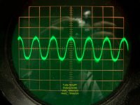
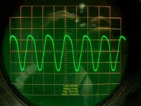
Okay, a starting point, good. Now, if the scope calibration is correct, then you have approximately 20mv pk-pk on the first amp and 32mv pk-pk on the second amp. Do the math and you have 0.0071 VRMS and 0.0114 VRMS output noise, this is quite high. Your S/N ratio (referenced to 1-watt) is only 52dB for the first amp and only 48dB for the second amp.
I think this would easily account for noticeable loss of inner detail in music recordings as the lower in level those parts are, the closer you get to the noise floor and intermodulation of the output noise with the actual signal. While you might not hear the hum at the listening position, you have pretty high limitations with the amps. Incidentally, what is the sensitivity of your loudspeakers and how far away is the listening position? Also, any idea on the noise floor in the listening room? Those noise figures would run me out of the house on my speakers (~95dB@1-watt) before playing any music.
So, what to do on rectifying the problems and getting better performance?
Well, I would recommend power supply first:
1- Get the plate supply sorted as many others have also recommended. A decent choke that can handle 200ma minimum and ~ 7-10H inductance. Don't overcap the rectifier tube, especially if you are using electrolytics. You should likely see a solid 375 volts output at load, which is fine.
2- Implement a dedicated DC filament supply for the 6B4G outputs. In general the 6B4G will never be quiet enough on AC filaments. Probably go with Rod's regulator boards as it's easy and has proven results.
3- Ensure your quiescent current flow is 80ma for the pair of tubes. That should be around 60 volts across a 750 ohm resistor (make it a 25-watt unit). Also use a bypass capacitor, 100uF should be okay.
You can run the better 6B4G tubes around 17 watts without issue (good ventilation expected). It's best to keep the cathode current lower and increase the plate voltage. They will still last longer this way and you'll get less distortion (I've measured it) as well.
With that sorted, look at the input/driver circuitry next:
4- Clean up the input amp. 15ma of current for the input amp is a bit silly, think about what you are driving and how much voltage swing you need. Single triode is preferable and 3ma is fine. Be sure to have adequate grid voltage so you can get proper voltage swing out to the phase inverter (without driving into class A2). It's a low mu tube (17). Plate curves shows 100 volts on the plate at ~3.2ma of current and -5 volts on the grid (1.62K standard value cathode resistor) and bypass it unless you plan to use some loop feedback. You want at least 100 volts on the plate load, a 47.5K load will sit around 152 volts. Calculate supply voltage for 152+100+5 = 257 volts at 3.2ma.
5- Re-examine the phase inverter/driver. First, remove the 317 regulator... they work fine for trickle charging small batteries. You'd be better off with a resistor there. Also note that the requirement here to drive the 6B4G push-pull pair is a minimum of 120 volts pk-pk. With the voltage swings required and the input capacitance of the 6B4G tube, you should have about 6ma of current here, a bit more is fine, i.e., if you prefer to keep the 7.5ma each. This should get you a pretty flat bandwidth past 40KHz with good iron. You should also add an AC balance pot to the phase inverter plate feeds (voltage supply into the wiper and the plate load resistors from each end of the pot to the plates). You can use this to balance out the drive as the output pair is rarely that closely matched. As you need 120V pk-pk output, the plate loads need to see about the same for good linearity. A total resistance of 20K would sit around 150V at 7.5ma. Using a 5K balance pot, the plate load resistors drop to 17.5K. Back to the plate curves, 125 volts on the plate at 7.5ma of current is -5 volts on the grid. We basically squeak by on this, but you don't have much plate supply to work with. This leaves you with 70 volts in the cathode circuit for the long-tail pair. A few options; 1- use a current source capable of handling the voltage. 2- Use a 5K resistor. 3- use a separate cathode bias resistor (and the grid resistors to it) of 332 ohms (5 volts at 15ma) and either a 15ma current source or a fixed resistor of 4.7K. Calculate voltage supply 150+125+5+70 = 350 volts at 15ma.
Based on what you have to work with, this is what I would start with (as what I usually refer to as backing into a design). This should yield a better performing amp and should get a reasonable S/N ratio from it, more like 80dB referenced to 1-watt. (I've managed this with a DC supply on a 6B4G SET). A solid 10-watts should be expected and power bandwidth should extend beyond 30KHz with the Dyna iron.
A note on the 6B4G tubes:
The NOS ones come is two basic flavors. First is a set of separate triodes (filament, grid, anode) in the same envelope and strapped in parallel. The second is the same as the typical RCA dual-plate 2A3, which is two filaments and two grids but one integrated dual-plate for them. Again, strapped in parallel. The problem is the filament wiring is also done one of two ways. I've seen some of the dual triode types where the filaments are wired in parallel, but also some where they are wired in series. Pretty certain that all of the dual plate 6B4G tubes have the filaments wired in series. In short, it's impossible to be lucky enough to get a pair that could cancel each other out. Hence, you need a DC supply if you want a quiet amp.
Hope the above is useful.
Regards, KM
thanks a lot Kmaier!
Rod's regulator would be probably too expensive for me as it would cost upward of 100$. Is there a cheaper option for this?
Rod's regulator would be probably too expensive for me as it would cost upward of 100$. Is there a cheaper option for this?
what do I need to change to acheive that ron?There are two glaring problems to be addressed. 1) The 6B4G's are being run way too hot, and 2) hum.
1) If the 6B4G's are to be kept, and they're staying in this chassis, then the 6B4Gs' quiescent plate dissipation has to be brought down to within acceptable limits. Running the 6B4G's with 20+ watts of plate dissipation will burn them up too quickly. Maybe 17W each would be OK, but the published limit is 15W, and that would be what I'd strive for. (Lowering the output stage B+ would also mean a slight reduction in input voltage required by the output stage, making it easier to drive. It would also slightly reduce the rp of the 6B4G's, which would help slightly with damping factor.)
Last edited:
I have done some reading. Am I wrong to think that the 60hz hum Ive measured in my amp is probably about this:
[2] induced hum 'bias' - where there is an essentially small A/C bias to the signal at 50/60 Hz, moving the signal constantly through different operating-points of the valves in the amplifying chain
The #2 induced hum/bias stands out as being at least as likely as #1. So much of our perception of the quality of an audio system comes from parts of the music waveform that cross zero, and are bracketed by a few millivolts around zero. Moving the absolute average to a wider range 'cuz of the 50/60Hz A/C bias effect ... definitely makes a difference. The human ear is remarkable in being able to effortlessly tune out the 50/60 Hz tone while listening to music.
Hi guys,
Things I am sure to do :
1- Cathode resistors will be change, as recommended multiple time, from 500R to 750R 25W
2- I will replace the choke to Hammond 159Q
3- LM317 will be remove and replace with a 750R 1W resistor. However, Kmaier recommend to rather use a 5k resistor here?
4- for hum, I will make sure to rewire the heaters wire
I am not sure about what to do with those points…
Should I still do :
1-do as rongon recommended in post 107 which is to add a 150R 10W before the 5ar4 tube.
2- at pin 8 of V1= 5ar4, theres a big 10 uf-600v caps. Should I still try removing the 10ufd/600volt cap at cathode of the tube rectifier?
3- consider changing R14 from 1k to 1500 ohms. `` You might consider changing R14 from 1k to 1500 ohms. That should reduce the current through the 6B4G's, which would get them running a bit cooler, and not so far over their plate dissipation limit.``
4-Take away the bypass capacitor C6 from across R13 and R14. Just remove it.
What should I do about those 4 points? Are those still relevant now?
About Kmaier post, point number 4 and 3. I am not sure what I have to change in the schematic to apply the point number 3 and 4 of kmaier post.
The only thing im not willing to do right now is spend close to 150$ for a filament supply. I would like to avoid doing this and see if, with all the other mods, I'm satisfied with the sound..
Any help would be greatly appreciated
thanks
With all respect, and please understand that I'm trying to be helpful here:
It's obvious that you don't understand the many clues that have been handed to you, from a number of people here. It's time for you to do some reading and learning on your own.
http://www.diyaudio.com/forums/tubes-valves/182614-looking-great-tube-amp-book.html
Valve Amplifiers, Fourth Edition: Morgan Jones: 9780080966403: Amazon.com: Books
This is the diyAudio forum, which means you really do have to DIY.
--
my goal is not to learn how a tube amp work, just improve a amp I already have and dont want to loose all this money with a not optimal design. As is, the amp is not good enough to use and not good enough to sell. I have 800$ already invested into this and I do not have multiple months/years to learn how a amp work before knowing how to improve this amp. I need a amp now...
Can someone ,who understand all thats been discussed here, apply the changes that was recommended by Kmaier and rongon and write them down on the schematic, that would be very great. I would be very glad. My technician could simply follow the schematic and apply the changes.
The only thing that I cannot do due to money limits is apply filament supply. I'm a student and really money limited.
Maybe thats asking too much, but I am really in a cul-de-sac here!
With all respect, and please understand that I'm trying to be helpful here:
It's obvious that you don't understand the many clues that have been handed to you, from a number of people here. It's time for you to do some reading and learning on your own.
http://www.diyaudio.com/forums/tubes-valves/182614-looking-great-tube-amp-book.html
Valve Amplifiers, Fourth Edition: Morgan Jones: 9780080966403: Amazon.com: Books
This is the diyAudio forum, which means you really do have to DIY.
--
Last edited:
I think the problem is you simply don't understand what you're posting or what anyone else is posting. When you showed enough interest to get a reasonable set of specifications, I took the time to give you feedback and redesign using what you have.
You can learn a lot by getting an old mid-50's ARRL Handbook, and it would have taken a fraction of the time to read the basic intro on electronics and the power supply sections (which would at least arm you a bit to understand what's being posted) versus the large amount of time you've spent on the forums and driving back and forth to your technician (so far).
I think pretty much everyone on the forums are helpful and willing to help, but when you make it pretty clear that you're only looking to have someone redesign your amp so you can have someone else fix it with the hopes of making it work to your expectations, you tend to lose most of the folks out here. After all, it is a DIY forum, not a free clinic.
Again, do a bit of textbook reading and then re-read some of the posts in this thread. Here's a good deal on a ARRL manual:
The Radio Amateur's Handbook Vintage 1957 Communication Manual ARRL Complete | eBay
Regards, KM
ok, fair enough.
Ill get the book and read it and see if I can understand all the help youv been posted.
What I will do is try to apply your points kmaier in your post and write it in the schematic.
I will just buy the book now.
I however dont trust myself enough to learn soldering in a possibly fatal tube amp where any error could kill me, but I will read the book to be able at least to understand what you guys talk about. but isnt the book really complicated or its for beginners?
thanks
I think the problem is you simply don't understand what you're posting or what anyone else is posting. When you showed enough interest to get a reasonable set of specifications, I took the time to give you feedback and redesign using what you have.
You can learn a lot by getting an old mid-50's ARRL Handbook, and it would have taken a fraction of the time to read the basic intro on electronics and the power supply sections (which would at least arm you a bit to understand what's being posted) versus the large amount of time you've spent on the forums and driving back and forth to your technician (so far).
I think pretty much everyone on the forums are helpful and willing to help, but when you make it pretty clear that you're only looking to have someone redesign your amp so you can have someone else fix it with the hopes of making it work to your expectations, you tend to lose most of the folks out here. After all, it is a DIY forum, not a free clinic.
Again, do a bit of textbook reading and then re-read some of the posts in this thread. Here's a good deal on a ARRL manual:
The Radio Amateur's Handbook Vintage 1957 Communication Manual ARRL Complete | eBay
Regards, KM
Last edited:
- Status
- This old topic is closed. If you want to reopen this topic, contact a moderator using the "Report Post" button.
- Home
- Amplifiers
- Tubes / Valves
- How to improve this 6B4G push-pull circuit