After 99 replies, seems nobody has bothered to ask the most basic of questions. The OP noted that he made some measurements and that nothing is really wrong, sans the poor perceived performance when compared to some class D amps. So I guess I'll ask.
What measurements did you make on the amplifiers and what leads you to believe that there's nothing wrong??? Some measurements that would be useful would include:
- Frequency response (at 1-watt)
- Output power before clipping
- Power bandwidth
- Signal to noise ratio (or at least output noise sans input signal)
- Distortion
Other bits of useful information:
- Does a sinewave look proper on a scope?
- Is the output signal symmetrical?
- Does the output signal clip symmetrically?
It would also be useful to post an actual schematic of the amplifiers as they are currently wired rather than have additional details dribble out over pages of replies. While I can certainly come up with a handful of concerns based on the posted schematic (and some recommendations for improvement), I'd prefer to know actual measured performance first.
Regards, KM
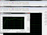
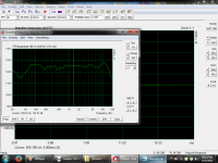
I did some measurments with the same speaker in the same room with the class d and the tube amp.
here's the measurments results.
Yes, a sinewave look proper too.
here's the measurments results.
Yes, a sinewave look proper too.
tube amp is the left one and class d right oneAfter 99 replies, seems nobody has bothered to ask the most basic of questions. The OP noted that he made some measurements and that nothing is really wrong, sans the poor perceived performance when compared to some class D amps. So I guess I'll ask.
What measurements did you make on the amplifiers and what leads you to believe that there's nothing wrong??? Some measurements that would be useful would include:
- Frequency response (at 1-watt)
- Output power before clipping
- Power bandwidth
- Signal to noise ratio (or at least output noise sans input signal)
- Distortion
Other bits of useful information:
- Does a sinewave look proper on a scope?
- Is the output signal symmetrical?
- Does the output signal clip symmetrically?
It would also be useful to post an actual schematic of the amplifiers as they are currently wired rather than have additional details dribble out over pages of replies. While I can certainly come up with a handful of concerns based on the posted schematic (and some recommendations for improvement), I'd prefer to know actual measured performance first.
Regards, KM
Attachments
Last edited:
okay great, can I use this one Edcor CXC100-7H-150mA or the hammond would be as good?
Power supply mods. Please examine the attached screenshots.
I modeled the psu with a 5H choke. If you decrease the value to 2H, it still works, but ripple goes up. Still not bad, with ripple to the output stage at 700mV (millivolts) and to the input stage 450uV (microvolts).
If you increase the choke to 10H, things look really good. Output stage ripple 127mV, input stage ripple 90uV.
It's obvious that the better the choke, the better the psu will perform. 7H 150mA would be good. The Hammond 159Q meets those specs and has a DCR of 100R.
--
I will learn one day for sure, but im a good friend to the technician, so its a situation where I dont mind going to him.
please keep on helping!
please keep on helping!
In that case, I agree with AJT. Or, be brave and buy a 50 value 1 Watt set of resistors from ebay, a soldering iron, some solder and learn to solder! This is a DIY forum !
It is much more fun that way than having to drag a technician to do 2 changes. We cant tell the technician to twist the heater wire better for example...
Where do you live by the way?
You sent us graphs showing frequency response of the speaker, showing how they differ if driven from different amplifiers. That tells me that the tube amp has no negative feedback loop around the OPT. We knew that already.
I'm not sure if I mentioned this before, but...
You should measure the amplifier (the device under test), not the speaker.
Take measurements at the amp's output terminals across a dummy load resistor.
I completely agree with kmaier, and will repeat what he asked, because he hit the nail on the head:
--Some measurements that would be useful would include:
- Frequency response (at 1-watt)
- Output power before clipping
- Power bandwidth
- Signal to noise ratio (or at least output noise sans input signal)
- Distortion
Other bits of useful information:
- Does a sinewave look proper on a scope?
- Is the output signal symmetrical?
- Does the output signal clip symmetrically?
It would also be useful to post an actual schematic of the amplifiers as they are currently wired rather than have additional details dribble out over pages of replies.
Since you already have a signal generator and an oscilloscope, you should be able to use an 8 ohm 25W resistor (mounted on a heatsink) as a dummy load (instead of a speaker) and follow this tutorial to take measurements on your tube amp.
[That 25W resistor will only be useful with weenie triode amps up to maybe 10 watts. DO NOT try to measure a high-power transistor power amp with such a small resistor, even if it's mounted on a heatsink.]
http://vibes.uml.edu/modules/Elaine...d_OscilloscopeWaveformGenWaveMeasurements.pdf
I hope that's helpful.
--
PS - Here's a picture of a DIY 8 ohm 250W dummy load. --
http://www.reelaudio.co.uk/images/photos/CarverTFM42/FinDummyLoad.jpg
--
Last edited:
You know, this forum is a fantastic source of information for the tube amp DIYer. What a great resource! I saw this thread -- http://www.diyaudio.com/forums/tubes-valves/257422-mullard-5-20-power-supply.html -- and thought that it might be applicable to the situation here. Sure enough, it is. Great information, at your fingertips! You gotta love them innerwebs.
Applying a little something I just picked up from that other thread, here's another power supply mod to improve the situation here...
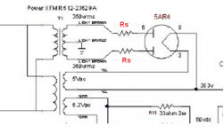
To use the 5AR4 rectifier tube properly, there should be series resistors on its plates. These can be used to reduce output voltage (which we actually need!) and will limit inrush current through the 5AR4, thus prolonging its service life (which would be a very good thing).
Added resistors are labeled "Rs" in red in the attached picture.
According to Chart III in the 5AR4 datasheet -- http://www.drtube.com/datasheets/5ar4-ge1959.pdf -- each Rs should be a minimum value of 125R. I guess that means there is no theoretical maximum value, so these resistors can be used to drop volts from the supply's output. Just what we needed to save those 6B4G's from an early grave. Try 150R 10W wirewound in each of the two plates in each 5AR4.
For 5U4GB (http://tubedata.milbert.com/sheets/093/5/5U4GB.pdf) use 50R 5W wirewound.
--
Applying a little something I just picked up from that other thread, here's another power supply mod to improve the situation here...
To use the 5AR4 rectifier tube properly, there should be series resistors on its plates. These can be used to reduce output voltage (which we actually need!) and will limit inrush current through the 5AR4, thus prolonging its service life (which would be a very good thing).
Added resistors are labeled "Rs" in red in the attached picture.
According to Chart III in the 5AR4 datasheet -- http://www.drtube.com/datasheets/5ar4-ge1959.pdf -- each Rs should be a minimum value of 125R. I guess that means there is no theoretical maximum value, so these resistors can be used to drop volts from the supply's output. Just what we needed to save those 6B4G's from an early grave. Try 150R 10W wirewound in each of the two plates in each 5AR4.
For 5U4GB (http://tubedata.milbert.com/sheets/093/5/5U4GB.pdf) use 50R 5W wirewound.
--
Attachments
Last edited:
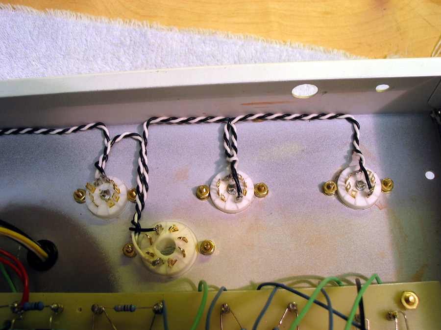
Layout issues?
This from costis_n got me to go back and look at your layout.
After looking at this picture --
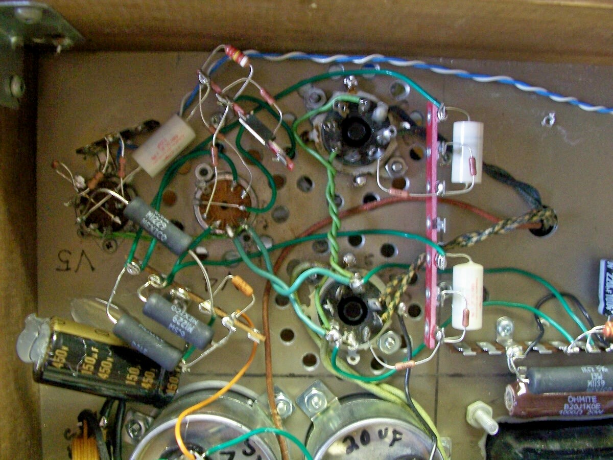
-- I think your heater wiring is likely to be injecting hum into the audio circuitry.
The heater wires should be tightly twisted together, into 'twisted pair.' It's easier to do this with solid core wire, as opposed to stranded wire.
The (tightly) twisted pair heater wires should be routed away from the audio signal circuitry. It's common practice to tuck the heater wiring into the corners and edges of the chassis, only coming into the center of the layout to get to the tube sockets. Then the heater wiring doubles back to the edge of the chassis, and travels along the edge until it comes to the next tube socket. Something like this --
Please take a look at this thread (it's a sticky in this forum):
heater wiring - the Good the Bad and the Ugly
There are pictures of 'good, better, best' heater wiring practice in post #2 and post #3.
Note that in post #20, kevinkr mentions that DHT tubes with filament voltages over 2.5V should be DC rectified. The 6.3V filament of the 6B4G DHT tubes makes them a bit of a challenge. Note that EL34 tubes are indirectly heated, so are easier to work with in this regard.
--
This from costis_n got me to go back and look at your layout.
We cant tell the technician to twist the heater wire better for example...
After looking at this picture --
-- I think your heater wiring is likely to be injecting hum into the audio circuitry.
The heater wires should be tightly twisted together, into 'twisted pair.' It's easier to do this with solid core wire, as opposed to stranded wire.
The (tightly) twisted pair heater wires should be routed away from the audio signal circuitry. It's common practice to tuck the heater wiring into the corners and edges of the chassis, only coming into the center of the layout to get to the tube sockets. Then the heater wiring doubles back to the edge of the chassis, and travels along the edge until it comes to the next tube socket. Something like this --
Please take a look at this thread (it's a sticky in this forum):
heater wiring - the Good the Bad and the Ugly
There are pictures of 'good, better, best' heater wiring practice in post #2 and post #3.
Note that in post #20, kevinkr mentions that DHT tubes with filament voltages over 2.5V should be DC rectified. The 6.3V filament of the 6B4G DHT tubes makes them a bit of a challenge. Note that EL34 tubes are indirectly heated, so are easier to work with in this regard.
--
Last edited:
ok, we can only do this:
- Frequency response half power bandwidth a 5 watts rms @8 ohms.
- Output power before clipping
I will post the result shortly. I hope its enough, but the other test I cant do...
- Frequency response half power bandwidth a 5 watts rms @8 ohms.
- Output power before clipping
I will post the result shortly. I hope its enough, but the other test I cant do...
If you can measure frequency response at 1W output (4V *peak* across the 8 ohm load resistor), and then measure frequency response at 5W output (9V peak across the 8 ohm load), that will be a useful comparison.
Please also take a picture of a 1kHz sine wave at 1W output and attach that to your next post.
Finally, please take a picture of a 10kHz square wave at 1.4V peak output (1V rms) and attach that as well.
--
Please also take a picture of a 1kHz sine wave at 1W output and attach that to your next post.
Finally, please take a picture of a 10kHz square wave at 1.4V peak output (1V rms) and attach that as well.
--
Last edited:
I did some measurments with the same speaker in the same room with the class d and the tube amp.
here's the measurments results.
Yes, a sinewave look proper too.
tube amp is the left one and class d right one
You might want to read this article, as it outlines exactly what's up. Atma-Sphere music systems, inc.
Essentially, the speaker is a Voltage Paradigm device, and the tube amp in this case is a Power Paradigm device.
The result is a frequency response artifact. This is why voltage feedback has been recommended, to try to create the correct voltage response in the tube amp.
The problem is that you may find that adding negative feedback has other deleterious effects on the resulting sound. In a word, it will get brighter even though the actual frequency response is unaffected. This is because the feedback will add some odd ordered harmonics, to which the ear is very sensitive.
To get around this you might consider a Zobel network to equalize the voltage/power issues in the problem area of the frequency response. Then you won't need the feedback with its attendant problems.
re.: Norman Crowhurst
ok, we can only do this:
- Frequency response half power bandwidth a 5 watts rms @8 ohms.
- Output power before clipping
I will post the result shortly. I hope its enough, but the other test I cant do...
You can measure output voltages to calculate output power, so also measure output noise (with the input shorted) and the 8-ohm load attached. Likely in the milli-volt range and useful.
Regards, KM
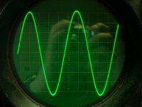
1-Sine wave 1Khz - 1W (2.8vrms).
2-Square wave 10Khz - 1 Vrms.
Output flat 20hz - 20Khz at 5Wrms (6.4vrms) @ 8 ohms.
Output clipping distortion appears at 10Wrms (9 vrms) @ 1Khz - 8 ohms.
we realized that the V1 in the amp 2 introduce distortion at 5W. so I will have to change the problematic tube.
2-Square wave 10Khz - 1 Vrms.
Output flat 20hz - 20Khz at 5Wrms (6.4vrms) @ 8 ohms.
Output clipping distortion appears at 10Wrms (9 vrms) @ 1Khz - 8 ohms.
we realized that the V1 in the amp 2 introduce distortion at 5W. so I will have to change the problematic tube.
Attachments
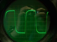
I see just a little High frequency loss, and just a little ringing from the transformer. Pretty good, and normal for a no-feedback amplifier.
So i think that your speakers like to see low source impedance, like most "normal" speakers. So you need something with feedbaxk, as atmasphere said.
Looking again at the schematic as it is, i think that you dont really need the first valve in parallel. You can reconfigure the first valve to be 2 stages one after the other. This will give enough gain to use feedback.
But then, you have 6 stages int the feedback loop, (1 & 2 in the 1st valve, 3 in 1/2 the phase invertor, 4th is the 6B4G, 5th is the transformer). Not good at all. Better to return the feedback to the right hand input of the phase inverter.
Last edited:
Basically, yes. This is the next step I would do. On the other hand,very difficult to do it over the internet.
You can start reading, get a soldering iron, a resistor and capacitor series, a scope and start reading the materials from the sticky topic "online learning for newbies"
You can start reading, get a soldering iron, a resistor and capacitor series, a scope and start reading the materials from the sticky topic "online learning for newbies"
What about the hum? Did you measure that?
--
You can measure output voltages to calculate output power, so also measure output noise (with the input shorted) and the 8-ohm load attached. Likely in the milli-volt range and useful.
--
hiWhat about the hum? Did you measure that?
--
I will try to ameliorate the wiring and see how the hum reacts. But the hum sound really low. I cannot hear it at all from the listening position.
I have two 6b4g and 2 6c4c
is that or 6b4g= 6c4c ???
I will test all the tube soon to make sure no other tube are problematic
So, great news for the amp I guess nothing is inherently wrong, just need to ameliorate the circuit?
Gee, and to think I've made amp measurements far too complicated over the past 40 years!
Seriously, what you measured so far doesn't tell much. The main reason I continue to ask for actual measurements around output noise is based on three things:
1- your initial post stating problems with low level detail
2- the fact you are using 6B4G triodes with AC filaments
3- your schematic shows output noise as less than 100mv
So, exactly what is the output noise and what does it look like on the scope?? Your signal to noise ratio pretty much defines the dynamic resolution of the amplifier. If I were to take your worst case value from your schematic, say 99mv, the amp would have a S/N ratio of ~29dB (ref 1-watt), which renders it useless. Even 1 mv output noise is high, and your S/N is only 69dB. My personal reference for anything 10-watts and under is 80dB S/N referenced to 1-watt. That means an output noise less than 283uv (yes, microvolts... or 0.000283 VRMS). To put it simply, you're not going to get anywhere close to that with AC filaments on the 6B4G tubes.
So until the actual S/N is known, making circuitry changes is a moot point, as you still haven't isolated the cause of poor low level detail (which is likely to be a S/N limitation). This is why I've asked twice for this measurement. I guess it's out of the question to know what the design parameters where for the initial design.
Regards, KM
- Status
- This old topic is closed. If you want to reopen this topic, contact a moderator using the "Report Post" button.
- Home
- Amplifiers
- Tubes / Valves
- How to improve this 6B4G push-pull circuit