The amplifier continues to draw current after power shut down.
This depletes the capacitors to around one or two Vbe drops.
There after the rate of discharge can be very slow.
no.or 1.2 volts....
One Vbe drop could be anywhere from 500mVdc to 800mVdc.
Two Vbe drops could be anywhere from 1000mVdc to 1600mVdc.
My statement said around one or two Vbe drops, which in my mind is around the voltage range of half a volt DC, to one and half volts DC.
NOT, your conclusion of exactly 1.2Vdc, as you have posted.
Stop trying to goad me into an inappropriate response.
Thanks guys.
It seems like I might be wise to add a resistor across both the + and - banks to deplete the charge more consistantly/rapidly. This means to my understanding that a small about of current from my power supply will be wated during use.
This loss is ok with me if it is tiny and I don't want to burn up my added resistor:
My PSU is 1000VA at 62VDC with 66,000uF per side. I could use maybe a 100K/5W resistor on each side?
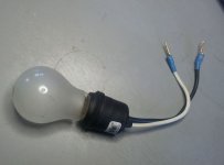
An inexpensive (< $1 US.) outdoor socket serves well for discharging. It's the second most used tool I have - behind only the soldering iron. I'm in the habit of using it even when I don't have to,
That's clever, very useful when building and testing PS without and with amps connected. Saves time.
cheers,
An inexpensive (< $1 US.) outdoor socket serves well for discharging. It's the second most used tool I have - behind only the soldering iron. I'm in the habit of using it even when I don't have to,
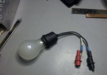
I use something very similar except I have longer leads and shielded alligator clips on the ends so I can clip it on to give it a chance to completely drain the caps if needed. Most times just a touch is enough but for really large caps, sometimes it takes a little longer. It doesn't take high voltage to make a good arc when dealing with large caps.
I use something very similar except I have longer leads and shielded alligator clips on the ends so I can clip it on to give it a chance to completely drain the caps if needed......


Attachments
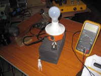
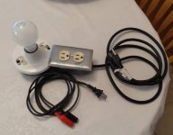
Here is a picture of the one I built. It has two outlets. The one on the right puts the light bulb in series for current limiting during start-ups. The outlet on the left puts the light bulb in parallel for draining caps. I made a few leads like the one in front from old lamp cords. I've also used the parallel setup for testing power supplies. You can adjust the amp draw with different wattage lightbulbs.
Attachments
Dim bulb?
I built one too just so I could see if the bulb dims when the PS is done charging; it is a great indicator!
I just want to know if my thinking is right here: if I use a 100K resistor across any one of the caps (one in each positive and negative bank) with 62VDC that 100K reisitor will only drain less than one mA during amp use and after the amp is shut down right? Quite a slow discharge... This would indicate to me I don't need a 5W resistor, not even close! Am I off base?
;
not at all, it is never a crime to use a 5 watter on application that calls for 1 watt, only space is your limit.....i do it all the time, gives me more peace of mind....
If my calculations are correct, 62V across a 100K resistor is only 38mW, .62mA. A 1/4W resistor is 125mW so that should be fine.
of course you are correct in your calculations......
using a higher wattage than what your calculations came up with
only means that your resistor will be running colder than otherwise,
you can choose...
Good to see all Badgers are "healthy".
No duds here.
In middle July , I will show my first single Badger build.
By "single" ... I mean a SUBWOOFER Badger.
I have the 1.7 cu.ft enclosure with a 10" Tang band driver all ported to
26hz , have the 400VA toroid ...
The only changes are a "hotter VAS" (56R at CCS) and single
100pF Cdom (NO TMC).
Since the PCB will be inside the sub, I'll glue the caps to reduce any
microphonics and use a PC switchmode PS oversized heatsink for VAS.
OP devices will be just 2 pair MT-200 sankens to give me
125W / 250W peak @ 6R with a 50-0-50V main supply.
I will post many photo's to show the forum just how good of a build
the "Bassbadger / WT-644f " combo can be.
Already tested the badger (outside the enclosure) with this setup ...
I can blow out candles @ 4 meters and shake the building with
ease. Badger is MUCH better than the bridged IC amp that originally
powered this logitech Z-5500 driver - a real upgrade (I built a much better
enclosure .. too.)
Good luck to all those who have built or (those about to rock -ac/dc)
---- I salute you !
OS
well, whatever, just do not poke your fingers on the boards when power turned off, that is not safe....
You now see the use (actually primary) for the blue/red leds.
LED glows - DO NOT touch. (told that to my kids)
.PS - shocked myself once , all my amps are now "christmas trees"
.My New amps actually combine LED function (voltage/CCS references) with the safety factor and "looks" (UV ,blue,green).
I just LOVE led's
.OS
You now see the use (actually primary) for the blue/red leds.
LED glows - DO NOT touch. (told that to my kids)
PS - shocked myself once , all my amps are now "christmas trees"
My New amps actually combine LED function (voltage/CCS references) with the safety factor and "looks" (UV ,blue,green).
I just LOVE led's
OS
almost forgot about that....thanks for reminding....
on to my second Badger build, ver. 2.4...
will run VAS abit hotter this time around...
- Home
- Amplifiers
- Solid State
- diyAB Amp The "Honey Badger" build thread