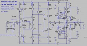
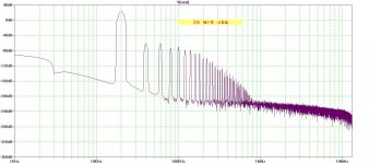
This is my first attempt to design a power amp without global NFB, 30W/8ohm and 60W/4ohm. It works in Class A up to full power on 8 ohm load and goes in Class AB on 4 ohm. Distortion does not change with frequency.
The gain block is a kind of my GainWire preamplifier and output is a novel output buffer working in class A. It uses separate power supplies for the input and output.
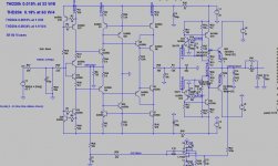
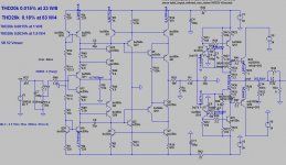
Here are two schematics, one with the volume control at the input, and other with the volume control after input gain block(current conveyor). The second one has advantage to have the signal/noise ratio constant over whole volume regulation and the nose is lower then the first schematic. The second one has to use DC servo to keep output near to zero voltage, this is needed because change the volume resistor value change output voltage a bit. The first schematic uses simple trimpot(P2) to set zero output voltage.
Thermal stabilization is obtained with two diodes(D1, D2) and it's quite stable. Here is ideal place for ThermalTrak output transistors from ONSEMI.
Damir
The gain block is a kind of my GainWire preamplifier and output is a novel output buffer working in class A. It uses separate power supplies for the input and output.
Here are two schematics, one with the volume control at the input, and other with the volume control after input gain block(current conveyor). The second one has advantage to have the signal/noise ratio constant over whole volume regulation and the nose is lower then the first schematic. The second one has to use DC servo to keep output near to zero voltage, this is needed because change the volume resistor value change output voltage a bit. The first schematic uses simple trimpot(P2) to set zero output voltage.
Thermal stabilization is obtained with two diodes(D1, D2) and it's quite stable. Here is ideal place for ThermalTrak output transistors from ONSEMI.
Damir
Attachments
-
 GainWire-ClassA-POWERamp-sch.jpg157.6 KB · Views: 1,285
 -
 GainWire-ClassA-POWERamp-DCservo-sch.jpg145.1 KB · Views: 1,229
 -
 GainWire-ClassA-POWERamp-Gain.jpg279.7 KB · Views: 1,118
 -
 GainWire-ClassA-POWERamp-FFT20k1W.jpg128.1 KB · Views: 978
 -
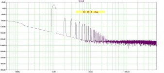
 GainWire-ClassA-POWERamp-FFT20k30W.jpg149.6 KB · Views: 915
 -
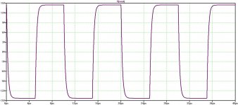 GainWire-ClassA-POWERamp-square.jpg100.2 KB · Views: 281
Very good
Excellent
Like last preamp.
Your designs are better and better.
Like teen prodigy;-)
Thanks Pawel, you are to kind.

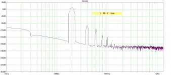
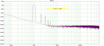
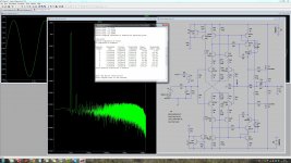
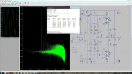
Harmonics profile is very good.
And it's even better at 1 kHz.
Attachments
Damir,
Pawel is correct........ clever circuit, very good performance, love the phase linearity in the audio band. I make it 1.35 degrees at 10KHz?
Hugh
Thank you Hugh for your kind words.
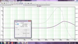
Yes the phase at 10 kHz is 1.35 degrees and 3 degrees at 20 kHz, could be a bit lower with the input shunt cap lower value. Maybe not to good idea to lover that cap to much?
Damir
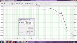
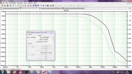
Picking in the gain response(at 15 MHz) worried me, so here is improved schematic. A cascode was added and cascode compensation, even if it was not needed to shield BC5xx transistors from to much voltage(as 30 V is not to much) but in that way behave of the input stage is tamed better. Surprisingly how an amplifier with no GNFB can easily oscillate.
All others data stayed the same, some phase shift was improved.
I think that this amp would sound similar to an excellent tube amp, but with more grip in low frequencies as the output impedance is quite low(54 mohm).
Damir
All others data stayed the same, some phase shift was improved.
I think that this amp would sound similar to an excellent tube amp, but with more grip in low frequencies as the output impedance is quite low(54 mohm).
Damir
Attachments
And it's even better at 1 kHz.
Can you explain why the harmonic profile is very good?
Can you explain why the harmonic profile is very good?
I suppose because no global negative feedback was used.
Can you explain why the harmonic profile is very good?
High order harmonics are quickly descending, and yes it is because lack of gnfb
")
Agree. But with higher THD, do you think this would 'sound' better Pawel?

rhetorical question?
No Pawel, not rhetorical at all, I am still open to views on this POV and I know that a lot of smarter people than me, particularly since my brain was broken a couple of years, would have a view and I would be most interested, without rancour, sarcasm, or argument.
Give it a go, mate.......!
Hugh
Give it a go, mate.......!
Hugh
Last edited:
No Pawel, not rhetorical at all, I am still open to views on this POV and I know that a lot of smarter people than me, particularly since my brain was broken a couple of years, would have a view and I would be most interested, without rancour, sarcasm, or argument.
Give it a go, mate.......!
Hugh
I would like to answer on that question, but my listening experience is not large enough to answer it with high enough certainty.
Damir
Picking in the gain response(at 15 MHz) worried me, so here is improved schematic. A cascode was added and cascode compensation, even if it was not needed to shield BC5xx transistors from to much voltage(as 30 V is not to much) but in that way behave of the input stage is tamed better. Surprisingly how an amplifier with no GNFB can easily oscillate.
All others data stayed the same, some phase shift was improved.
I think that this amp would sound similar to an excellent tube amp, but with more grip in low frequencies as the output impedance is quite low(54 mohm).
Damir
Damir,
I have built quite a few open loop amplifiers from completely zero feedback to
nested / local FB types as you have here.
IME it's a good idea to simulate the front end voltage amplifier and the OP
buffer separately to see how they are affecting the end result.
Most of the distortion will come from the OP stage, as such the voltage
amplifier can be simplified dramatically and still be way below the distortion
of OP stage.
I can post an example tomorrow of an IP stage that has from 0.004 to
0.0004 at 20kHz / 30V pk depending on config that is very simple if you are
interested.
WRT sounding like a tube amp, it's very difficult to predict. There are many
differences in design, it may well sound worse than a simpler global
feedback amp.
cheers
Terry Demol
I believe that the major benefit is that the interaction to the speaker is isolated to the OPS.
The major problem in this is to make an IPS with good performance and low output-impedance. I have tried to make the DADOD IPS work with "my" OPS, but it is troublesome due to the NON voltage source nature of the Gain cell. and fitting an open-loop OPS to that (the IPS) is very degrading in terms of performance and complexity.
For now I have made a good performing VFA sort of folded cascode gain-cell (IPS) to dive my OPS
Attachments
Last edited:
Damir,
I have built quite a few open loop amplifiers from completely zero feedback to
nested / local FB types as you have here.
IME it's a good idea to simulate the front end voltage amplifier and the OP
buffer separately to see how they are affecting the end result.
Most of the distortion will come from the OP stage, as such the voltage
amplifier can be simplified dramatically and still be way below the distortion
of OP stage.
I can post an example tomorrow of an IP stage that has from 0.004 to
0.0004 at 20kHz / 30V pk depending on config that is very simple if you are
interested.
WRT sounding like a tube amp, it's very difficult to predict. There are many
differences in design, it may well sound worse than a simpler global
feedback amp.
cheers
Terry Demol
Yes Terry, please post your example, power amp without GNFB is new for me(I made an preamplifier without GNFB and it sounds wonderful).
It is only my hope to get the sound similar to a tube amp.
regards
Damir
OMG.... edited my last post only to add to the IPS OPS confusion...
"The major problem in this is to make an IPS with good performance and low output-impedance." This should be about the OPS...!!!
This is then more on my sort of parallel symmetric folded cascode Voltage gain-cell.
At higher voltage-swings and higher frequencies the distortion performance is still very very good, main reason is that the circuit is always class A, so the hard correcting of switching in the output-mosfets is not needed.
I really do like the separation of Voltage and current amplification, this is for me the Key to make better amplifiers.
I really fail to see the need or purpose to get the IPS involved in Speaker control and OPS correction. I see this as a local job for a well designed OPS.
Attachments
Last edited:
- Status
- This old topic is closed. If you want to reopen this topic, contact a moderator using the "Report Post" button.
- Home
- Amplifiers
- Solid State
- GainWire-CLASS-A-poweramp NGFB