Ok I found the averaging/FFT option buttons, shame on me - it is clearly described in the manual. 
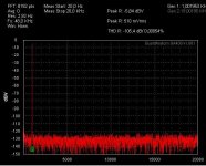
There is a very slim sweet-spot THD-wise both in 48Ksps and 192Ksps mode, and the volume producing lowest THD is just different at 192Ksps. After I found that out I was able to get loopback THD ~ 0.0007% at 192Ksps too.
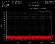
If the test frequency is set to an integer multiple of the frequency resolution (SR/FFT) then indeed the windowing function seems unnecessary. THD remains very low with no windowing ("rect"). However if the test frequency and its harmonics does not fall right into the FFT's bins then THD skyrockets with the windowing disabled.
Anyways I'm very pleased with the QA400 so far. Had some trouble with the original USB cable but now it works perfectly with a shorter/higher quality cable (had no drops since then).
There is a very slim sweet-spot THD-wise both in 48Ksps and 192Ksps mode, and the volume producing lowest THD is just different at 192Ksps. After I found that out I was able to get loopback THD ~ 0.0007% at 192Ksps too.
If the test frequency is set to an integer multiple of the frequency resolution (SR/FFT) then indeed the windowing function seems unnecessary. THD remains very low with no windowing ("rect"). However if the test frequency and its harmonics does not fall right into the FFT's bins then THD skyrockets with the windowing disabled.
Anyways I'm very pleased with the QA400 so far. Had some trouble with the original USB cable but now it works perfectly with a shorter/higher quality cable (had no drops since then).
Have you noticed that on the page of the QA190, the last 2 pictures are of the next update of the program QA400? The v1.067.
An externally hosted image should be here but it was not working when we last tested it.
The LF rise seems to be related to external pick up of "stuff". I found that position of the box and choice of BNC as well as lead dress and location in the room and on the bench seems to radically change the LF. There are some posts in this thread that show nil LF rise...
Would this be a viable isolation option? anyone tried it? IOGEAR - GUWIP204 - Wireless 4-Port USB Sharing Station | Wireless USB Hub | USB Hub | USB Switch
It looks interesting but the reviews say otherwise: IOGEAR GUWIP204 Wireless 4-Port USB Sharing Station - Newegg.com
No indications that it would be high speed.
No indications that it would be high speed.
To work there would be a driver to hijack the USB and send it out the network. There will be issues with throughput that will make it difficult on WiFi for high speed. USB 3 is a whole different issue with a different hardware interface. I know of no USB 3 audio interfaces yet. There are no compelling reasons to make one.
If the reviews were better I would get one. They are too iffy at this stage. However its much cheaper than the isolator I know works.
Sent from my Nexus 7 using Tapatalk
If the reviews were better I would get one. They are too iffy at this stage. However its much cheaper than the isolator I know works.
Sent from my Nexus 7 using Tapatalk
...no doubt the QA400 provides good spec for the money.
And when using levels of 500mVrms my unit is really providing a nice sweet spot.
But for real life applications it is a little bit naked and not robust enough.
Large input signals can easily damage it. The manual tells in other words, better do not use it for measuring anything else than a wire between input and output.
Input/Output level adjustment is possible only by software and comes by the expense of reduced SNR and resolution.
Filtering of HF residuals when looking at class D amps is not there at all.
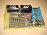
So I decided to build buffers and filters.
The output buffer allows a wide output range from zero to +/-5Vp without noticeable change in behavior.
The input filter is 5th order, flat up to above 50kHz, but fades 200kHz with more than -40db and 400kHz more than -70db.
It allows measuring signals from line level up to approx. 100Vpk.
The buffers & filter also protect the QA400 in case of heavy melt down events of the DUT.
Overall a slight worsening of the noise is there, but still fine for distortion measurements.
Attached some pictures and results.
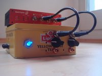
The performance is stable over very wide ranges of input and output voltages.
...ready to measure future class D projects ..
And when using levels of 500mVrms my unit is really providing a nice sweet spot.
But for real life applications it is a little bit naked and not robust enough.
Large input signals can easily damage it. The manual tells in other words, better do not use it for measuring anything else than a wire between input and output.
Input/Output level adjustment is possible only by software and comes by the expense of reduced SNR and resolution.
Filtering of HF residuals when looking at class D amps is not there at all.
So I decided to build buffers and filters.
The output buffer allows a wide output range from zero to +/-5Vp without noticeable change in behavior.
The input filter is 5th order, flat up to above 50kHz, but fades 200kHz with more than -40db and 400kHz more than -70db.
It allows measuring signals from line level up to approx. 100Vpk.
The buffers & filter also protect the QA400 in case of heavy melt down events of the DUT.
Overall a slight worsening of the noise is there, but still fine for distortion measurements.
Attached some pictures and results.
The performance is stable over very wide ranges of input and output voltages.
...ready to measure future class D projects
..Attachments
That's interesting. Care to share a schematic?
Of course I can share the schematic.
Very straight forward, nothing that I would call key know how.
Attached the most updated schematics, the filter function now fades out the 200kHz with -39db and 400kHz with -69db. Function is now flat at all poti positions.
In reality I used different OP amps. LM4562 for the output buffer and OPA2134 for the filter. But basically lots of OP amps will do the job.
Suppy is +/-9V from two 9V batteries.
For the poti of the output buffer one might consider a lower value, because the 1k resistor towards the OP amp impacts the log characteristic - but also with a 10k poti it is perfectly fine and I had it available. Also the 10k avoids unnecessary loading of the QA400.
But important is to use the right type of potis.
Funny thing: Some quality types caused k2,k3 around -80db, while some old low cost types turned out to be simply trouble free...
Attachments
Nicely executed. I like the casework. Is the input filter to remove stuff that might impact the measurements like switchmode amp noise? I noticed that you also have diodes at the inverting inputs of the opamps. That's a neat protection trick. Unfortunately inverting amplifiers are going to be low impedance and that can impact some measurements with devices that have high internal impedances. The pot is your primary input divider in this circuit. With an inverting amp at the input higher impedances may be possible with some scaling. Noise would be the downside. The input filter could be on the output of the opamp with the opamps you are using with few negative effects.
Yup, it is intended for measurements on classD amplifiers.Is the input filter to remove stuff that might impact the measurements like switchmode amp noise?
That's also why I did not take any measures to ensure a high impedance.
Focus is on filtering, low distortion and protecting the QA400.
- Home
- Design & Build
- Equipment & Tools
- QuantAsylum QA400 and QA401