Try to manipulate the models of the 3055/2955 until the glitch dissapears: take parameters one by one from a set of transistors that do not show the glitch and include them in the 3055/2955 model and run the sim.
I'm not even certain of the quality of the models, and since I have no idea of the real meaning of each parameter, I would be screwing up the existing models, more than they may already be and make them even less representative of the real thing.
I will try other models. But I wish there was a known good set of them to use, and avoid using the screwed up ones.
That simulation ran without any such artefacts with the mjl4281/4302 from bob cordell's collection, but the 3055/2955 that I use are from onsemi.
Well, I didn't have many choices of models for the 2n3055/mj2955. And apparently there is something wrong with at least one of them, and likely both.
Those models being from onsemi, for the 2n3055a and mj2955, by modpex.
One other model on hand is a 2n3055 that is supposed to be from ST, but that one has far fewer parameters, so I'm not certain of its accuracy and completeness of its compliance with the real thing.
However just for kicks, I tried using that ST 2N3055 instead of the 2N3055A modpex from onsemi, but they are too different from each other, even more than the 2 modpex models, so I was unable to bias the amp properly to try this.
Then short of 2N3055/MJ2955 models on hand, I figured let's try the MJ15015/6 instead. Those are also modpex from onsemi, but perhaps better, and they have a smaller difference between the 2 (npn vs pnp).
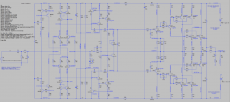
So I biased that thing just fine, and the crossover distortion artefacts on the square wave are gone. It works quite nicely and it looks like a slew rate of over 45V/us (input and feedback filters disabled for DC coupling).
With those models, the thd on 4ohms load @ 20k has also dropped further to 0.001525%. A mere 15ppm, not bad at all I think, as it only about doubles on the 2ohms load, more or less, so it is quite good enough to bridge a bridge on 8ohms and still get full power at very reasonable thd.
I'm attaching a screenshot of that sim schematic. This is of course a 4 pairs output and that would be an other build. The quasi remains a good one to make.
Those models being from onsemi, for the 2n3055a and mj2955, by modpex.
One other model on hand is a 2n3055 that is supposed to be from ST, but that one has far fewer parameters, so I'm not certain of its accuracy and completeness of its compliance with the real thing.
However just for kicks, I tried using that ST 2N3055 instead of the 2N3055A modpex from onsemi, but they are too different from each other, even more than the 2 modpex models, so I was unable to bias the amp properly to try this.
Then short of 2N3055/MJ2955 models on hand, I figured let's try the MJ15015/6 instead. Those are also modpex from onsemi, but perhaps better, and they have a smaller difference between the 2 (npn vs pnp).
So I biased that thing just fine, and the crossover distortion artefacts on the square wave are gone. It works quite nicely and it looks like a slew rate of over 45V/us (input and feedback filters disabled for DC coupling).
With those models, the thd on 4ohms load @ 20k has also dropped further to 0.001525%. A mere 15ppm, not bad at all I think, as it only about doubles on the 2ohms load, more or less, so it is quite good enough to bridge a bridge on 8ohms and still get full power at very reasonable thd.
I'm attaching a screenshot of that sim schematic. This is of course a 4 pairs output and that would be an other build. The quasi remains a good one to make.
Attachments
btw: I forgot to mention, I removed all the protection from the amp before grafting on that output stage. Since this is so different, the protection also requires a significant change and it would be much more complex.
Can anyone help adding a proper protection on that topo?
Can anyone help adding a proper protection on that topo?
Since I haven't been able to make the simulation work for the ground bridged version from the quasi based on the elektor amp, I've been pursuing the "john ellis" grounded bridge complementary amp and this works beautifully so far.
I have solved the few issues, such as having a center point between the rails without having a center tapped dual supply, and the rather high thd @ 20k/8ohms that was accompanied with a somewhat limited slew rate and a more than questionable stability margin. I had been able to bring thd down a lot and slew rate up, but at the expense of thd near 1%. We can do much better than that.
So I've tried various things and made some compromises and I think I arrived at something pretty nice now.
While doing various measurements, on dissipated powers and watching out for vce exposures on transistors, I found that it won't be possible to make use of the bc550c/560c types for the diff amp and although the 1st vas transistor could be one of them, I didn't see any big enough advantage in that spot, so I figured it'd better stay as bc546b/56b type. The current mirrors can definitely use the 550/560 and it does work better on the lpt mirror with them than the 546/56, so better use them there.
I found that with the rails sagging from the 70V, plus the overhead from the emitter resistors on the outputs, that the 3055s would only get exposed to some 61 or perhaps 62V of vce, but that may be more on reactive loads, I haven't tried that yet. I did add 2.5ohms of series resistance in the psu to make it more realistic and sag under load.
In any case, that amp should be provided with a stiff psu, especially if it is to be loaded with 4ohms. I hope the 2.5ohms series resistance in the psu isn't overly optimistic...
So the screening for the 3055s won't have to be too drastic, as I'm sure most of them will handle well over the 60V anyway.
I have done some testing with the protections turned on, partially and tried on some values, and found that it really trashes the signal, not matter how high above the normal usage we make its threshold. Plus it makes for such an awful signal when it really activates. Far more uggly than simple clipping. The earlier issue with the clipping having been solved, I have tested clipping, with protections disabled, and it's stay "clean" without artefacts, when good models are used.
Now the action of the vi limiter is nowhere near as clean as the clipping is. And it starts acting partially way before its actual threshold, so it dirties the signal much too early and the available power is very low without additional distortions.
If there is any way to clean up the act of that vi limiter, let's look at it. I have tried adding the diode clamps on the vas, but that doesn't change anything and they're not needed for sticking, as I haven't had any.
So what could be done to make the limiter behave better? If we can't make it work cleaner than that, then an other protection scheme is in order.
For now, let's say that this amp works quite beautifully, for example I get 223W on 8ohms at 20khz with thd at some 0.015..%, and that was obtained with the compromises as I explained earlier, with a phase margin now around 31degrees (instead of - something before), so although it's not some 45 or 50degrees, this should be stable enough.
I have to redo tests for slew rate, inter-modulation distortion and other torture tests on capacitive and inductive loads, but it seems about ready to go into pcb layout.
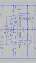
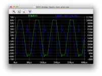
Trying to get the protections working on the John Ellis bridge. I partially enabled the VI limiter, keeping it in its simplest form to look at its behavior when acting. I unlinked its resistors going to the rails and the resistors/diodes going to ground, so what's left is only the very basic current limit.
I chose values so it won't act at all on the 8ohms load, so it works fine there and the amp clips cleanly without the limiter interfering.
I upped the load at 4 ohms and the protection starts acting where it should, right below where it would naturally clip, so I could see the behavior.
What I don't understand is why the negative side doesn't limit as neatly as the positive side does. The limiting on the positive side looks nearly the same as if the amp was clipping, but the negative side shows a slight delay in its action and then limits to a lower level than on the positive side and there is a little bit of ringing before it settles to the limiting level.
I also looked at the dissipated power in the vas transistors, drivers and outputs, and I can see that the effect of the limiter on the dissipated power in the outputs isn't what it should be, at all.
To push it into hard limiting, I brought the load to 1ohm, as if it was nearly a short, and the dissipation in the outputs is alarmingly high, such as over 3 times the capability of the 3055s (more than 360W per).
This can't work that way, as it won't protect against such overloads, the protection doesn't do its job properly.
I tried inserting base resistors before the drivers, but placed them between the vas and the limiters. That didn't help.
Just in case, I unhooked the small delay cap on the negative side from the sensing resistor, and that caused oscillations where it should act, so those caps are necessary.
I made a copy of the BC546B/56B models and made a slight adjustment to their BF and VAF parameters, to make them the same and BF a bit higher as if they were 46C/56C types, just to see how that would work. But that too doesn't change anything.
I had thought about a different way to make this type of protection to act. By adding transistors to short out the vas bases instead of the drivers bases. Perhaps this way to limit would be more gentle and would behave better without causing the large increase in power dissipation in the outputs.
If a limiter causes an increase in power dissipation, and doesn't prevent the destruction, then it's useless.
The thing is, I know how I could make the positive side change to act on the vas base, but I don't see how to do this properly, in a symmetrical enough way, on the negative side.
If we can't get such an ordinary limiter to work properly, then some other kind of protection needs to be worked out.
Any ideas on this?
Attachments
The Crimson Elektrik method used on their CE1704 module protects superbly but I've never figured out how it works. When the output is shorted, the drive gets removed somehow, but there's no relays. You have to power down for a minute and it comes back to life. There's a few (inaccurate?) scribbled circuits around, and there appears to be a thyristor made from 2 bipolars that may be at the heart of it.
Not very much diy info to be found about that crimson stuff. I guess they are really commercial and not diy.
I only found a VII version of a schematic, and if this is right, then they use the same vi limiting scheme, more or less, although just slightly simpler, but not really different.
We want the show to go on when the amp gets overdriven or overloaded in any way, unless the output is totally shorted, the sound should continue to come out. So crowbars and other such schemes are not welcome. Besides, with a crowbar, the amp still requires limiting, or the crowbar would instantly blow it.
The issue here, besides the odd behavior on the negative side, is that the limiter does limit the amplitude of the signal, but not the dissipated power in the outputs, and that's not a way to do soa protection for sure.
Something isn't right. And although I have simplified the limiter to only sense current, its action would be the same wouldn't it?
I am experimenting using an extra transistor shorting the vas input and for now, only from the positive side of the limiter. However at the moment its action causes oscillations.
The limiter doesn't act at the same level on the negative side as it does on the positive.
I think that due to the non symmetrical topo of the vas, and the fact that the drivers don't tie to the output but rather to each other, we can't have the limiters act exactly the same on both sides. I tried evening this out by inserting a resistor after the sensing resistors on the negative side, and this does re-establish a more equal action, but then I tried to look at this action at various frequencies and the behavior gets quite uggly at 20hz, with oscillations and stickyness. I added clamp diodes on the vas, but that has no effect.
I was trying to think of a different way to sense the output current and use this to clamp the driver bases together rather than independently to the output. I haven't come up with anything so far, but this could be something to experiment with.
I tweaked the sensing resistor values so they act early before clipping on a 4ohms load, so I could see the action behavior. When going back to 8ohms load, the limiter doesn't act and the amp just clips, fairly cleanly and reasonably.
On the 8ohms load with the closed loop gain the way I have it now and a few tweaks on the compensation, an input signal of 1.45V peak gives about 212W, and the thd @20hz is only 14.5ppm, almost 15ppm @1khz with about the same output power, however thd increases a lot @20khz at nearly 0.7% and a slightly lower power of about 207W.
I'm not sure the thd @20khz can be helped much without serious changes in the compromises I've made. As I've tweaked several things to get more phase margin with lower thd overall. This input level of 1.45V is a little below clipping, which happens a little higher with a little more than 1.5V for an output power a little over 227W (8ohms).
This is still beautiful though, but we need a properly working limiter that won't misbehave that way.
Not very much diy info to be found about that crimson stuff. I guess they are really commercial and not diy.
I only found a VII version of a schematic, and if this is right, then they use the same vi limiting scheme, more or less, although just slightly simpler, but not really different.
There's normal V/I limiting used on the Crimson circuit, yes, but there's also a latch that stops all dissipation. I'm not sure how T17/T18 latch but when they do, T2 and T6 turn off, removing drive to the output stage.
Crimson were/still are a commercial company but this CE1704 was a module for DIY also.
Last edited:
There's normal V/I limiting used on the Crimson circuit, yes, but there's also a latch that stops all dissipation. I'm not sure how T17/T18 latch but when they do, T2 and T6 turn off, removing drive to the output stage.
So if I get this right, then it means that as soon as the limiter detects the very first tiny bit of overload, it will remove the drive and latch on in that "position", meaning no more sound, the show stops right there.
If this is the case, then it's not the type of protection that I'd be looking into. I would want the amp to protect itself, but not to stop working at the very first sign of an overload.
I'd be curious to see what the regular vi limiter does on well known amps. I'll have to test a few on that.
I suspect they may also misbehave in a similar way as I am experiencing now in this sim.
I tried it at various frequencies and it may look fine at low frequencies, although not always without causing oscillations. it looks worse as frequency increases.
I suspect they may also misbehave in a similar way as I am experiencing now in this sim.
I tried it at various frequencies and it may look fine at low frequencies, although not always without causing oscillations. it looks worse as frequency increases.
I think an action on the input stages instead of the drivers/pre-drivers bases should be more gentle and perhaps less stressful when applying limiting on detected overload.
I would not favor at all something that latches on and stops the show. The only thing that should shut down fully is for example on DC detect on the outputs or over-current detect from output short.
We need an amp that self protects, but keeps on going, unless there is something very badly wrong with it, and an overload from over driving or overly heavy load must not be considered a failure, just an abuse by the user and the amp should continue while it protects itself.
Perhaps something to look into closer, if it truly never interferes in normal use and does protect in case of real need.
The "John Ellis bridge" clips rather gracefully and works great (in the sims), but the addition of the vi limiter trashes that and when it acts, the behavior is not good at all. I am thinking this may be due to the non symmetrical vas, and probably some other things due to the way the bridge works. I want to make this work and it must be protected properly, so a proper method needs to be found. One that doesn't trash the performance, lets the amp work normally under all "normal" circumstances, all the way to clipping, but does act without any adverse effects when needed.
The "John Ellis bridge" clips rather gracefully and works great (in the sims), but the addition of the vi limiter trashes that and when it acts, the behavior is not good at all. I am thinking this may be due to the non symmetrical vas, and probably some other things due to the way the bridge works. I want to make this work and it must be protected properly, so a proper method needs to be found. One that doesn't trash the performance, lets the amp work normally under all "normal" circumstances, all the way to clipping, but does act without any adverse effects when needed.
The nice thing about a "latch" type trigger is that one can never blame it for bad sound quality.
It is either "not triggered" or there is no sound. No argument.
That's true and the key is to make sure it doesn't act on any normal usage.
There is also a "latch" on the output current detection of a Mission and some others.
I'd like to look at some designs and try to understand its underpinnings
This may actually work better than trying to make a vi limiter transparent and properly behaved.
So far, no matter how I tweaked that limiter, it caused a lot more troubles than it solves. Perhaps on a fully symmetrical vas it would be more graceful when acting, so I think the ordinary limiter isn't the appropriate choice here and other options must be attempted.
I was able to put John Ellis's bridge in a bridged bridge simulation and it works fine. I wonder how it would work in case of action of a latch, because both bridges would be fully independent and the latches not acting in concert, but this may not be so much of an issue, if one bridge follows the other...
I wouldn't worry so much about getting a VI limiter to behave perfectly. If they're a bit asymmetric, or have a bit of overshoot or sticking when they activate, so what? You want them to behave as if they are not there for normal loads, and protect adequately when the amp is overloaded. There will be distortion then. Take a VI limiter that looks 'perfect' into a resistive load and put a lagging phase angle on it. Speakers have been known to do that. You'll see spikes that go to the rail. And hear them, too.
- Home
- Amplifiers
- Solid State
- Amplifier based on 2N3055