Hello friends:
I read again the cookbook and after replaced ZD3 and R2 for a potentiometer and get then 15V, jumping R2 the intensity remained high (is a botched job that I hope to resolve more later). I´d like put measures in schematics but I don´t know do it.
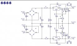
The resulting measures take alls to gnd with jmp 01 and 02 open and main potentiometer at twelve o´clock, are:
Output transformers: 22,62V
PSU rail 15V
Top of the LED1, 4,11V
Between LED1 and VR1: 2,33V
VR1
Leg 1 = 0V
Leg 2 = 2,33V
Leg 3 = 0V
Bottom of jumper 01: 5,75V
Bottom of jumper 02: 1,41V
Top of jumper 01 (from LDR): 13,5V
Top of jumper 02 (from LDR): 14,1V
Between R5 and Q4: 4,1V SUSPECT!
Between R6 and Q5: 2,14v
Current acroos jumper 01 0mA
Current across jumper 02 25mA DANGEROUS!
At this time don´t replaced any parts, I think is better the experts look first.
Any suggestion besides replace the bcs?
I read again the cookbook and after replaced ZD3 and R2 for a potentiometer and get then 15V, jumping R2 the intensity remained high (is a botched job that I hope to resolve more later). I´d like put measures in schematics but I don´t know do it.
The resulting measures take alls to gnd with jmp 01 and 02 open and main potentiometer at twelve o´clock, are:
Output transformers: 22,62V
PSU rail 15V
Top of the LED1, 4,11V
Between LED1 and VR1: 2,33V
VR1
Leg 1 = 0V
Leg 2 = 2,33V
Leg 3 = 0V
Bottom of jumper 01: 5,75V
Bottom of jumper 02: 1,41V
Top of jumper 01 (from LDR): 13,5V
Top of jumper 02 (from LDR): 14,1V
Between R5 and Q4: 4,1V SUSPECT!
Between R6 and Q5: 2,14v
Current acroos jumper 01 0mA
Current across jumper 02 25mA DANGEROUS!
At this time don´t replaced any parts, I think is better the experts look first.
Any suggestion besides replace the bcs?
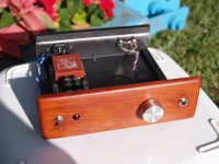
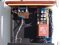
Finally I chose another pcb that I had at home and I started again carefully.
I detected two mistake choosen parts in the old.
The new PCB works great, but I struggled to match the channels. I'll go to a friend's house with scope when I get appropriate 2M2 potentiometers.
The important thing is that the sound is really good. Now it's time to test LS buffer, buffer-LS-buffer and find my favorite. Then I´d like put remote control, another battle.
Thanks to SP and ZM. The work is really fantastic.
Best regards
P.d:
One LDR have the dot in the other side.
......
One LDR have the dot in the other side.
bummer

PS - sorry , I didn't got that post from 2-nd december
Hi Jose. Enjoy !
You don't need 2M2 potenciometers...
See
http://www.diyaudio.com/forums/diyaudio-com-articles/168796-poor-serbian-mans-optical-attenuator.html
especialy below part that explain this picture:
http://www.diyaudio.com/forums/images/articles/opticalattenuator/original/18.jpg
You don't need 2M2 potenciometers...
See
http://www.diyaudio.com/forums/diyaudio-com-articles/168796-poor-serbian-mans-optical-attenuator.html
especialy below part that explain this picture:
http://www.diyaudio.com/forums/images/articles/opticalattenuator/original/18.jpg
Last edited:
Buffer PSU
¡Happy new year!
I´d like built in my own board (matrix dots) this PSU for a headphone amp but I´d like too can adjust the voltage between +/- 9 V to +/- 15 V or so. for test sound. ¿Can I put trimers in any place of circuit? This way is very confortable.
Thanks a lot.
¡Happy new year!
I´d like built in my own board (matrix dots) this PSU for a headphone amp but I´d like too can adjust the voltage between +/- 9 V to +/- 15 V or so. for test sound. ¿Can I put trimers in any place of circuit? This way is very confortable.
Thanks a lot.
")
It's udailey, but check this statement from him http://www.diyaudio.com/forums/grou...mfortable-passive-pre-amp-51.html#post3629586 .Uriahp or Uriah Heep?
- Home
- Source & Line
- Analog Line Level
- Poor Serbian Man Optical Volume Control