Two suggestions:
1)......2)
Thanks Bolserst!
Ill give it a go tomorrow... (just back from the gym and the treadmill)...
Before you spend up on those expensive 18mH inductors, have a read of this thread:
http://www.diyaudio.com/forums/multi-way/199658-woofer-resonance-notch-filters.html
http://www.diyaudio.com/forums/multi-way/199658-woofer-resonance-notch-filters.html
I am cowboy, i finally found my saddles....21 & 69 Hz with the help on a little bit of more load in series with the speaker cable.
But the lowest value seem to be strangely low, 27 Hz.
I use two vents ID70 at this point 160mm length which should be equivalent to one vent 105mm ID90 according to the WinISD0.44Beta I have been using. Calculating backward from PeteFrontiers 105mm ID90 vent and 33Hz the program says a 100 liters box.
Calculating 27Hz, 2 x 160mm ID70 i get a box size of 148 liters. 50% more than it "should be". Reading some posts here i get the feeling that the stuffing of the box does not change the resonance frequency that much but maybe it doe in my case. 25mm of soft glasswool afround the cabinet and most of the part behind the stringer loosely stuffed with lambswool behind a polyester "cloth", the area around the vents unfilled.
Maybe I anyway should start to unfill the box, as i dont want it to be too damped to loose efficiency...
Guidance?
Attachments
Last edited:
Before you spend up on those expensive 18mH inductors, have a read of this thread:
Hi Neighbour
Those 18mH don't have to be very expensive - they can have very high DC resistance and be quite cheap if they were made that way. They can even be wound by finding a plastic former and right gauge of wire, a chart and wind away - parts available from Jaycar I would think.
Re that thread, seen it, but they have kind of missed the point (and it is a stunner) - but at this stage I am keeping my powder dry as we are working on a White Paper that have a much wider view of the topic because it has application(s) that the thread has not even touching on.
BTW, I am in Prestons.
Cheers, Joe
")
I'm in St Marys
Cheers, Pete McK
Hi Pete. Come around some time - I'm here 90% of the time and just next to the M7.
Cheers, Joe
Hi Joe, how is the testing going?
The testing looks like happening very soon. The measurement and modelling should gives us the Crossover values required. The topology is already decided, so it will look exactly like the Mk5, but it comes down the the component values that will be different. I am hoping that the High-Pass to the Tweeter won't change and that the those five components will stay the same, but that may be a bit optimistic. We shall see.
I may actually show the modelling values her first - BUT recommend that nobody actually builds it like that. When the actual Crossover are made and actually tested (and listened to), there will almost certainly be values that will be tweaked. For example, in the Apollo 'Signature' Crossover upgrade (a commercial product) that consisted of 13 components, two needed to be tweaked. So that is a good guide.
But it is exhaustive and concentrated work, but when it all comes together, it is also very satisfying.
Cheers, Joe
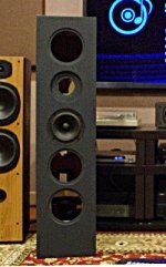
Looking forward to "hearing" the results, I have built my boxes both Elsinore and Hamlets so just waiting on the final spec before ordering the parts. I noticed that you flush mounted the speakers with this design. I'll have to modify mine to match.
Thanks for the hard work looking forward to reading your findings
Thanks for the hard work looking forward to reading your findings
MK5 filter + Bolserst mod + JoeR:s amendments
Hi Sibbeli (that asked for the filter design again) and the rest.
Here is one example of the MK5filter with both Bolserst mod and Joes amendments to it. Actually its the list that made up my filters.
Cheers
/H
Hi Sibbeli (that asked for the filter design again) and the rest.
Here is one example of the MK5filter with both Bolserst mod and Joes amendments to it. Actually its the list that made up my filters.
Cheers
/H
Attachments
The internal size of the Elsinore box ex speakers etc would be something like 78 liters. Looking at the figures in the thread with port sizes like 90mmID by length 105mm etc calls for a box size of 101 (up to 108 from other figures) liters. The stuffing should not do that much. Explanation anyone, are the figuers on the Peerless elements wrong or what?
The internal size of the Elsinore box ex speakers etc would be something like 78 liters... calls for a box size of 101 (up to 108 from other figures) liters. The stuffing should not do that much. Explanation anyone, are the figures on the Peerless elements wrong or what?
No, this is entirely intended. The Elsinores are not a classically 'lined' enclosure and more resistive as a result - it will slow down the internal velocity and make the enclosure look larger than it really is. Quite a lot larger in fact.
What is not usually understood well, and is a curious fact, that the box tuning of the vented/reflex box is entirely down to the box and is totally independent to the drivers used. So that any driver fitted to that box, the alignment will indeed change but not the box tuning frequency. So if it is 33 Hertz it will always stay 33 hertz, but the response may of course be entirely different. Sealed boxes are different, where the single peak in the box tuning is dependent on both the driver and box volume. But with vented enclosures, the saddle tuning frequency is independent of the drivers. Not the peaks above and below the saddle, they will change with drivers.
So this is a major difference between vented and sealed boxes - and it also explains why vented boxes are more flexible and also explains why it can also go wrong so much more easily. Talk about a double-edged sword.
Cheers, Joe
Hi Sibbeli (that asked for the filter design again) and the rest.
Here is one example of the MK5filter with both Bolserst mod and Joes amendments to it. Actually its the list that made up my filters.
Cheers
/H
My main concern is with C, R and L directly across the Voice Coils of the upper two MidBass drivers. This LCR is in parallel with the Voice Coil (not objecting so much with the 33R resistors)and it goes against the philosophy of what is intended with the Mark 5 Elsinores and that is the current going through the Voice Coils be the same (or constant) with frequency. The 33R resistors are not so much of a problem as they draw linear current (zero current phase angle), but the C and L shift the current phase with R becoming the limiter (so I would keep R as high as I could get away with).
Let me put it this way, if you study the overall picture of the Crossover, you will see that all the correction stuff is seen directly by the amplifier, with the exception of the LC in the High-Pass to the Tweeter. But this LC is way below the pass band of the Tweeter and so its function has little effect compared to anything that is in-band, which the LCR to the two MidBass drivers is.
The intention is clearly this, that current through the Voice Coils be constant and hence the voltage across the Voice Coil will be as well. Note the italics through and across.
Drivers are current devices and yet we insist on modelling using voltage models and I have attempted to reverse that. Current through a Voice Coil is always the same thorough the Voice Coil. But voltage is not and indeed somewhere in the middle of the VC the voltage has halved. But the voltage across the VC should ideally be the function of the current through the VC, and it would if we were driving from a current source (current amplifier), so what we are trying to achieve is pseudo-current drive. That LCR now upsets that idea/intention. The voltage across the VC as a function of current is upset by that LCR combination.
The problem largely (but not wholly) the highish inductance of the Peerless driver, and the new SB driver has a lot less. But with the Mark 5 it was always intended that they be pointed down the room more and avoid pointing directly to the listener and the 4KHz energy handled that way rather than adding the LCR. But with the new driver we will have an expected 1mH or larger series inductor not working against a rising inductance in the VC and get a more predictable roll-off. External inductance is good, internal is not - and for more than one reason.
But with the Mark 6, we are soon to see what we have got as the critical moment has almost arrived where we start the testing and modelling.
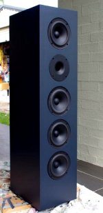
Paris has finished the boxes.
Cheers, Joe
Last edited:
I am cowboy, i finally found my saddles....21 & 69 Hz with t the lowest value seem to be strangely low, 27 Hz...
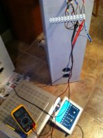
There is one other method you can use to determine your vented enclosure tuning if you don't have a microphone measurement system. It is a visual method in which you look at the motion of the woofer cones as you sweep up and down in frequency in the 20hz - 50Hz range. At the tuning frequency of the enclosure the woofers are loaded by the Helmholtz resonance and there is a dip in the woofer excursion-vs-frequency curve.
Example excursion curve attached below...
To make it easier to observe the cone motion, I usual stick a small piece of white masking tape on the cone or dust cap. Then just turn up the volume on your sine wave sweeps until you can clearly see woofer cone motion above and below the minimum at the enclosure turning frequency.
Attachments
sorry to interfere, and that I don't have time to read a lot of posts ...
[/B]
The Mark 6 will use a new driver but still same Tweeter/Waveguide combo. As far as I know, the Peerless driver is still available, but it became apparent that the SB driver should also work in that same enclosure and that it has some features that I believe will make the Mark 6 an improvement. I never intended there be a Mark 6, but then again... one should never say never.
Cheers, Joe
- Home
- Loudspeakers
- Multi-Way
- The "Elsinore Project" Thread