There is quite strange for me that someone may appreciate such manipulated and obvious distorted still picture after a Darbee processing.
The program/algorithm is called ALCE2 by Roberto Bigano and is a Photoshop Plugin - that photo is just an example they show and just to be obvious, maybe too obvious. But the effect can be dialled in to be a lot more subtle than that example, from 0% to 100%.
It is the same with the Darbee processor - you can set it between 0 and a max of 100. I haven't seen it yet but I have spoken to an Oppo distributor who has seen it with the '103 Darbee and he said the best effect without exxageration is when setting it to 25-30. If you set it to zero, it does nothing at all.
But some people will want to really wind it up, but I suspect you and I will treat it the same way we add a little salt to our food and if you add too much it will be worse than too little.
I will be getting a '105 Darbee during the 2nd part of February. The ship is due to arrive in Melbourne in the middle of the month.
Cheers, Joe
Joe,
I've been meaning to ask your subjective opinion/experience of using these large value Murata multi-layer ceramics with analog circuits. If I correctly recall, you use them to bypass analog circuits as well as digital. There are those out there who say they would never use ceramics with analog circuits, however, my mind is very open about it, and I have come to respect your audio observational skill.
I can only say one thing: USE THEM !!!
You won't regret it - and they are nothing like the old ceramics - and yes I agree, I wouldn't use those either.
Cheers, Joe
They act like the closest thing to an AC crowbar known to man reducing HF noise to immeasurable levels. I only wish they were available in much larger values...
You are right about the size, this is one instance it does matter.
These caps actually do two things at the same time.
Let's say you have a regulator, most of them usually struggle to have sufficient bandwidth, so at HF their impedance goes up. Then you also has centimeters or even inches of track to the power input on the IC or DAC. Those tracks will have some inductance, not a lot, but important at HF and VHF.
Put those stacked film caps as reasonable close to the target, the the output impedance plus any latent inductance (the track) will give it a 2nd order filter effect that attenuates noise that originates from the power supply.
At the same time, ground noise coming out of digital (switching) chips, especially DACs - and you have a very Low Z ground path for back-EMF coming out of the DAC. These things are like Black Holes to noise coming from two directions.
But you are right, the effect, both ways, is maximised by using a LOT of capacitance.
It also works very well with analog circuits, but the biggest pay-off is on the DAC.
Modifying SMPS or even converting them to linear, makes less difference than this little device does when used properly. This is an elegant solution to noise management and just shows if you throw money at something is not always that smart. Anyway, that is my opinion.
Cheers, Joe
.
My opinion, in other words- RUN AWAY!
I understand where you are coming from - but use these where there is no ripple current and I use a minimum of double voltage rating and they are fine. I have literally used thousands of them, strictly according to those conditions, and failures has been very rare indeed.
Cheers, Joe
Pile 'em high
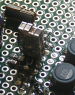
Here's my latest build - there are 20 1206 22uFs (4wide, 5high) sitting on top the AD8017 in SOIC8. In the background is the inductor (two ferrite beads) feeding the power in. Missing are the lytics which go in parallel to maintain the 'crowbar' effect down to the bottom end of the audio band.
Here's my latest build - there are 20 1206 22uFs (4wide, 5high) sitting on top the AD8017 in SOIC8. In the background is the inductor (two ferrite beads) feeding the power in. Missing are the lytics which go in parallel to maintain the 'crowbar' effect down to the bottom end of the audio band.
Attachments
The program/algorithm is called ALCE2 by Roberto Bigano and is a Photoshop Plugin - that photo is just an example they show and just to be obvious, maybe too obvious. But the effect can be dialled in to be a lot more subtle than that example, from 0% to 100%.
It is the same with the Darbee processor - you can set it between 0 and a max of 100. I haven't seen it yet but I have spoken to an Oppo distributor who has seen it with the '103 Darbee and he said the best effect without exxageration is when setting it to 25-30. If you set it to zero, it does nothing at all.
But some people will want to really wind it up, but I suspect you and I will treat it the same way we add a little salt to our food and if you add too much it will be worse than too little.
I will be getting a '105 Darbee during the 2nd part of February. The ship is due to arrive in Melbourne in the middle of the month.
Cheers, Joe
Yeah you don't have to set full pop. The ideal i find largely depends on the panel/projector and the source quality. Either way, once setup right, if you turn it off, the picture looks "broken" without it...
Is that what they call the Manhattan style ...?Here's my latest build - there are 20 1206 22uFs (4wide, 5high) sitting on top the AD8017 in SOIC8.
 ,
, Ask anyone who works on Panasonic plasma tv's(competently, at least), and they will tell you, as I will, emphatically to avoid those Murata and other brand smd ceramic caps of 0.47uf & higher. Even the 50V ones can't stand up to even 12VDC continuous, no ripple voltage exposure for more than a year or two, without a lot of luck. If you just think about how thin the ceramic layers need to be to jam that much capacity into such a small package(probably close to a molecule thick in that 10uf/25V 1206-package cap), you'll realise why it's a miracle they don't dead short on first charge. My opinion, in other words- RUN AWAY!
Which caps X5R?
X7R MLCCs are used on high reliability products all the time with no problems, I would suspect either they are using the cheapest caps or some other problem.
Here's my latest build - there are 20 1206 22uFs (4wide, 5high) sitting on top the AD8017 in SOIC8. In the background is the inductor (two ferrite beads) feeding the power in. Missing are the lytics which go in parallel to maintain the 'crowbar' effect down to the bottom end of the audio band.
This is a clever and recommended way to make large ceramics capacity. Unfortunately after one solder together all these caps, there is not possible to desolder it again. Well, it is, but the rate of destroyed components it may increase quite much... If one will then want to experiment something, then it should build up another one...
I will suggest that when you solder together two or many such caps, only place a kind of spacer in between the caps, and make a soldering bridge over to connect/solder the caps together. Then remove the spacer. So it will be more easy to remove the soldering bridge and separate the caps. As spacer one can use a piece of thick paper, or something which will not melt under soldering process. Something around 1 mm it may be right enough...
So, it may look more like the Sears tower, and it will be less Manhattan style...
Last edited:
Adding spacers degrades the performance though - more resistance and inductance. I'm not worried about re-using individual caps but have re-used blocks of them. They're not very expensive these ones - a reel of 2000 costs around $35. But I do hanker after the top of the range ones (100uF) which go for six times that
Adding spacers degrades the performance though - more resistance and inductance. I'm not worried about re-using individual caps but have re-used blocks of them. They're not very expensive these ones - a reel of 2000 costs around $35. But I do hanker after the top of the range ones (100uF) which go for six times that
When you solder so the caps, there is almost nothing left as total inductance in the packet.
A half mm or 1 mm in between is also nothing as resistance or inductance as well, related to all the construction...
But up to you, of course.
Yeh probably not the best example, they are used, we had some on a job that looked like trump towers., when I first saw them I thought it was a joke.....But the only way
1mm is a huge distance for these sort of things, inductance wise.
I agree that one mm it may be huge distance inductance wise in Ghz or many hundreds Mhz range, but is not the case in this application here...
At least it may be half mm, or so, but anyway this is not so important.
for any decoupling application inductance is the killer and stray parasitic inductance can make your decoupling totally useless. The determining factor for high speed digital design is the signal rise time, and the knee frequency derived from this. Look up all the documentation on decoupling and you will see that minimising inductance is more critical that ultimate capacitance value...
On the Oppa I believe there are 50MHz clocks so yes 1mm is critical in decoupling applications, and on a cap stack like this would render the stack pointless due to parasitic inductance....
Remember for digital decoupling parasitic inductance must be minimised.
On the Oppa I believe there are 50MHz clocks so yes 1mm is critical in decoupling applications, and on a cap stack like this would render the stack pointless due to parasitic inductance....
Remember for digital decoupling parasitic inductance must be minimised.
There is quite strange for me that someone may appreciate such manipulated and obvious distorted still picture after a Darbee processing.
I have being myself in photo world for a good while now, and I`m enough experienced with photography processing, and so on, but I will never accept a so rough manipulated image on my displays. If is this what mean Darbee "improvements", then this will never be something for me.
In motion pictures these rough image manipulations, sharpness increasing and contrast exaggerations it does not looks for a viewer so bad, because the fast changing in picture composition, or a distributed a attention on many other fields. But on still picture this is really bad!
I will never want or pay for such...
Coris, in movies, as in music, our world is quite imperfect: The light is not right, the focus is wrong, the dynamic range is restricted, there is too much contrast, too much reverb, the cameraman is hangover, the music recording/mixing engineer is stoned, etc., etc., etc.
So, what do we do? We take charge ourselves and we modified to our own taste. We correct some mistakes made, we make our moving pictures and music recordings more attractive, more lively, less dead and less badly fabricated.
We trust ourselves more than we trust others.
We live in an imperfect world ...
for any decoupling application inductance is the killer and stray parasitic inductance can make your decoupling totally useless. The determining factor for high speed digital design is the signal rise time, and the knee frequency derived from this. Look up all the documentation on decoupling and you will see that minimising inductance is more critical that ultimate capacitance value...
On the Oppa I believe there are 50MHz clocks so yes 1mm is critical in decoupling applications, and on a cap stack like this would render the stack pointless due to parasitic inductance....
Remember for digital decoupling parasitic inductance must be minimised.
You have right!
I do not know exactly what the circuit shown by abraxalito does, but I suppose it works in analogue domain, and maybe DAC post processing. Here it may not be about clock frequencies, but a HF noise into few Mhz. If is something which process clock of 54Mhz or so, then I agree with you that parasitic inductance of the decoupling caps it may be important.
Coris, in movies, as in music, our world is quite imperfect: The light is not right, the focus is wrong, the dynamic range is restricted, there is too much contrast, too much reverb, the cameraman is hangover, the music recording/mixing engineer is stoned, etc., etc., etc.
So, what do we do? We take charge ourselves and we modified to our own taste. We correct some mistakes made, we make our moving pictures and music recordings more attractive, more lively, less dead and less badly fabricated.
We trust ourselves more than we trust others.
We live in an imperfect world ...
- Home
- Source & Line
- Digital Source
- Oppo's BDP105 - discussions, upgrading, mods...