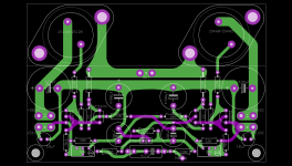
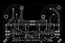
If the picture shows components' side of the PCB, the VFETs are OK, but please check everything else - you don't have GND pin on the PCB, the input BC547 on the left side of the board has 22R between its B and E, 10K is also connected to that B, etc...
Error #0 (too many errors)...
Error #0 (too many errors)...
Juma, I have changed the layout to reflect the correct pinout for the VFET - TO3s.
(My EAGLE - CAD-software-library does not contain them.)
Can you please once more put an eye on it?
Best regards - Rudi_Ratlos
...ratlos?
Last edited:
... ratlos ( needing advice)?
Not at all! But the one, who asked me to do a layout for him, shall please take a thorough look at the EAGLE-schematic that I have sent him, before he says: "It is o.k., go on!"
This is no amplifier that I will build for myself.
Best regards - Rudi_Ratlos
Not at all! But the one, who asked me to do a layout for him, shall please take a thorough look at the EAGLE-schematic that I have sent him, before he says: "It is o.k., go on!"
This is no amplifier that I will build for myself.
Best regards - Rudi_Ratlos
Attachments
New schematic of the amp with changes described in today's EDIT note in the post #1 of this thread.
A classical Zobel at the power output port may cure the instability in the amp using the original schematic. Is there an intrinsic hum voltage at the power output in the absence of loop feedback? If your answer is no, then your PSU will be ideal to power the SIT amp shown at BAF2013 by Mr. Pass.
No.A classical Zobel at the power output port may cure the instability in the amp using the original schematic.
Absurd...Is there an intrinsic hum voltage at the power output in the absence of loop feedback?
Hum like generg heard with his SIT amp operating w/o loop feedback as designed by Mr. Pass who explained the hum insertion as due to the low plate [drain] resistance of a triode [SIT].No.
Absurd...
PSRR is a property of the circuit/device and if it's not as high as you wish it to be, you take care of it in the PSU.
When it's cold you don't nag how feet are badly designed. You put your shoes on...
beautiful.Sound advice. Thank you.PSRR is a property of the circuit/device and if it's not as high as you wish it to be, you take care of it in the PSU.
When it's cold you don't nag how feet are badly designed. You put your shoes on...
Still waiting for the big heatsinks so I took the time to listen some more to the amp and experiment with the PSU. The question was if it's worth to use the cap multiplier for the Vds (+/-25V) PSU. And it was - there's a lot less ripple, better sound (cleaner, better imaging) but I was not ready to accept 4V loss accross the MOSFET so I made a BJT version of cap mult. which has only 2.1V voltage drop at 2.4A current draw (so now I got Vds of +/-24V) and the ripple voltage of 2mV peak-to-pek (reduction of about 50db - 300 times).
Additional benefit is a longer time needed to establish Vds which gave me an opportunity to use bigger gate caps (C12,16 from sch in post #1 are now 220uF) and charging resistors (R2,11 from sch in post #1 are now 3k3) in front end PSUs cap multipliers so that FE voltage has a lot less ripple now too, without breaking a timing balance between the Vgs and Vds.
I used Fairchild's 2sc5200/2sa1943 (O grade) and BC547c/BC557c with hfe of about 450 (lower hfe means higher voltage drop across cap multiplier).
This is what I got now instead of 0R5/5W resistors between the 33mF caps :
Attachments
Last edited:
Still waiting for the big heatsinks so I took the time to listen some more to the amp and experiment with the PSU. The question was if it's worth to use the cap multiplier for the Vds (+/-25V) PSU. And it was - there's a lot less ripple, better sound (cleaner, better imaging) but I was not ready to accept 4V loss accross the MOSFET so I made a BJT version of cap mult. which has only 2.1V voltage drop at 2.4A current draw (so now I got Vds of +/-24V) and the ripple voltage of 2mV peak-to-pek (reduction of about 50db - 300 times).
Additional benefit is a longer time needed to establish Vds which gave me an opportunity to use bigger gate caps (C12,16 from sch in post #1 are now 220uF) and charging resistors (R2,11 from sch in post #1 are now 3k3) in front end PSUs cap multipliers so that FE voltage has a lot less ripple now too, without breaking a timing balance between the Vgs and Vds.
I used Fairchild's 2sc5200/2sa1943 (O grade) and BC547c/BC557c with hfe of about 450 (lower hfe means higher voltage drop across cap multiplier).
This is what I got now instead of 0R5/5W resistors between the 33mF caps :
Nice idea, as usual, simple and effective (and useful as a "retrofit" mod for other project that could benefit from a lesser ripple).
A question: does the cap multiplier likes to have big caps after it? What could be the difference between a (relatively) low value (e.g. 10uF) film cap and a big (20-40 mF) elcap supplying a class A stage?
Guido
Thanks for the proposal, but that way (fixed output voltage) I'd have to accept higher losses in PSU to allow for electrical network's fluctuations (it's -15%/+5% around here) which is not very appealing solution.If you are going to the bother of making a capacitance multiplier, then go the
extra inch by putting a shunt reference in parallel with the reference capacitor
(also include an output capacitor).
DC regulation is also important with SITs.
This way (mildly floating PSU voltage) there's a nice tracking in timing and value between the FE/Vgs and the Vds voltage which works lovely here.
- Status
- This old topic is closed. If you want to reopen this topic, contact a moderator using the "Report Post" button.
- Home
- Amplifiers
- Pass Labs
- VFET PP amp