I once had a friend that work in a small store with 5 employees . His boss would walk by him to put a memo in his mail box rather than speak to him.
Did he also wear gloves?
Thanks Mike.
I was/am interested as per recent discussion to see effects with differing loads.
Also discussion of advantages or not of this network, as opposed to standard output circuit.
Dan,
I guess standard depends upon your viewpoint - this kind of o/p network is standard for me just now - you had better define another standard.
As for the loads I'll show 1uF and then 5uF each in parallel with 8R.
As my Voltage source in spice does not suffer from instability we could easily agree with Pavel & John & Wayne from my spice simulations that no o/p choke is the best arrangement but to make this a reality in real life we will have to design an amp that really does not need any extra FB loop stability or just doesn't have loop FB
")
As for discussion, my understanding is that the 1st snubber & the choke help with amplifier stablity while the damping resistor across the choke and the 2nd snubber help with stability in the final o/p going to the speaker but there is also an interaction between these elements.
Agree .....
How about some examples of the limits? Undamped 5uF, what works and what are the tradeoffs?
Sorting out some technical papers, I found this 'very beginning' of my association with Jack Bybee and his 'products'. It has been a long strange trip that I still enjoy.
Love that second paragraph.
First, how about your cable measurements, JN?
For the guys with the proper equipment (there are at least three here).
Settle on a certain cable, measure and exchange notes.
Characteristic Cable Impedance:
http://www.ietlabs.com/pdf/application_notes/035023%207600%20Characteristic%20Cable%20Impedance.pdf
More useful equations and info:
http://www.ietlabs.com/pdf/application_notes/030122%20IET%20LCR%20PRIMER%201st%20Edition.pdf
Merry Christmas
George
We Don't All Have Non Loop Feedback Amplifiers....
This series of Mosfet amplifiers found quite common usage in PA applications back in the day....early eighties.
There are still plenty out there in faithful service in many installed and mobile pub/bar hire rigs.....every local PA audio board level tech/service center will know how to cure them.
In this case, most of the cure is physical.....dud solder joints (soldered then cut, flux left behind.....these things get to run red hot for hours......der.
The B+ and B- 80V rails are long thin tracks, closely adjacent to each other,.....heaps of dust, smoke machine fluid, humid room.....der.
Cure is to beef up the long tracks with telephone wire strand the full length, cleanse and then liberally apply conformal coating.
Tweaks is choosing input and NFB shunt caps, local rail decoupling electros, and they're good to go long term.
They are then quite bulletproof, and have that old school, clear, pretty clean, mosfet sound.....good amplifiers.
These amplifiers get used with a range of loads, combined with reasonably long speaker cable runs, in what can be a magnetically (and AC supply) noisey environment....dimmers hash, bar fridges....etc.
I have never heard these amps to misbehave.

Anyway, there is a very wide range of speaker loads out there, some particularly/spectacularly low impedance, and also can be very reactive . (There is discussion about speaker loads and amplifier current capability over at SQ vs Measurements thread)
So, Mike, you are very good at SIM, I thought a discussion of a representative range of speaker loads might be interesting.....ie simulated real loads.
Typical 1/2/3 way, planar electro and magnetic, a few renowned 'difficult' speakers ie Wilson, Quad, etc, combined with differing output networks, with differing circuit values....that sounds like a lot of permutations, but should be easily whittled down.
The point of this, is it worth doing some investigation into optimizing output networks according to the particular amplifier and the particular loudspeaker that is connected, via a particular cable ???.
Is it worth fitting networks to amplifiers that do not otherwise need it ???. .
Or is the generic kind good enough for those of us stuck with those simply awful loop feedback amplifiers ???.
Just thinking out aloud.
Dan.
Yes, my understanding already, also.Dan, As for discussion, my understanding is that the 1st snubber & the choke help with amplifier stablity while the damping resistor across the choke and the 2nd snubber help with stability in the final o/p going to the speaker but there is also an interaction between these elements.
This series of Mosfet amplifiers found quite common usage in PA applications back in the day....early eighties.
There are still plenty out there in faithful service in many installed and mobile pub/bar hire rigs.....every local PA audio board level tech/service center will know how to cure them.
In this case, most of the cure is physical.....dud solder joints (soldered then cut, flux left behind.....these things get to run red hot for hours......der.
The B+ and B- 80V rails are long thin tracks, closely adjacent to each other,.....heaps of dust, smoke machine fluid, humid room.....der.
Cure is to beef up the long tracks with telephone wire strand the full length, cleanse and then liberally apply conformal coating.
Tweaks is choosing input and NFB shunt caps, local rail decoupling electros, and they're good to go long term.
They are then quite bulletproof, and have that old school, clear, pretty clean, mosfet sound.....good amplifiers.
These amplifiers get used with a range of loads, combined with reasonably long speaker cable runs, in what can be a magnetically (and AC supply) noisey environment....dimmers hash, bar fridges....etc.
I have never heard these amps to misbehave.
Anyway, there is a very wide range of speaker loads out there, some particularly/spectacularly low impedance, and also can be very reactive . (There is discussion about speaker loads and amplifier current capability over at SQ vs Measurements thread)
So, Mike, you are very good at SIM, I thought a discussion of a representative range of speaker loads might be interesting.....ie simulated real loads.
Typical 1/2/3 way, planar electro and magnetic, a few renowned 'difficult' speakers ie Wilson, Quad, etc, combined with differing output networks, with differing circuit values....that sounds like a lot of permutations, but should be easily whittled down.
The point of this, is it worth doing some investigation into optimizing output networks according to the particular amplifier and the particular loudspeaker that is connected, via a particular cable ???.
Is it worth fitting networks to amplifiers that do not otherwise need it ???. .
Or is the generic kind good enough for those of us stuck with those simply awful loop feedback amplifiers ???.
Just thinking out aloud.
Dan.
Last edited:
First, how about your cable measurements, JN?
Which ones, I've done quite a few.
Alas, I followed a very strict regimen of understandings and controls such that:
1. Others could REPEAT the exact same measurements without worrying about whether they did the same thing.
2. A theoretical basis for the measurements which sets bounds on what is being measured.
3. An understanding of the level of accuracy of the measuring tool within the expected range of the instrument.
4. An understanding of how confounders will alter the results of the test.
5. An analysis of how to control for the expected confounders.
6. A test regimen which is designed to determine if the test instrument is behaving in an expected fashion. For inductance measurements, this entails measurements on either side of the expected range where readings need to be accurate.
To wit: Actual testing requires VERY controlled and VERY repeatable tests using the exact same cable under the exact same conditions.
Ed has provided initial measurements which were 3.5 ORDERS OF MAGNITUDE higher than reality. This demonstrated a lack of understanding of what inductance is, how inductance is measured, what the limits of the test equipment were, and even what the instrument maker recommends as far as test selection for the entity being tested.
Then, out of nowhere, he provided 5 incredibly blurry pictures of something. One looks like a shorted cal test, and the other 4 have various readings of something. It's possible to discern the readings, but they are meaningless without information, and impossible to reproduce.
So what exactly am I supposed to do?? Flail away, trying to guess at how to do a test?? Give me a break. You may work like that, Ed may.
The measurement being discussed requires a lot more information to produce meaningful results consistent with another's tests. Wire gauge, centroid spacing, pitch length, dielectric coefficient, jacket thickness, how the wire is coiled, how to control the coiling, how the meter works given capacitive and eddy loss confounders.
It requires attention to details. Apparently, what you consider to be a "practical engineer" is one who ignores details, ignores theory, ignores instruction manuals, ignores advice, ignores whacked out test plots, and forms one's own opinion, however misguided and erroneous it is. You also defend your idea of a "practical engineer" against "criticism" DESPITE THE FACT that a test error caused results almost 3,000 times larger than reality.
I am not that kind of engineer. And I do not work with any engineers who so blindly disregard actual engineering.
I am not going to spend my time venturing into your fantasyland of irreproducible results. If you decide to do some actual engineering, let me know. If Ed wants to actually detail pics with enough information to allow others to examine the test setup in detail, he can do so.
I will certainly spend time performing well controlled and well documented tests, discussing what is found with everybody who wants in on the discussion. Real engineering, not simple flailing. Flailing appears to be your bailiwick, and Ed seems to be doing same at the moment. Others are not.
jn
For the guys with the proper equipment (there are at least three here).
Settle on a certain cable, measure and exchange notes.
Characteristic Cable Impedance:
http://www.ietlabs.com/pdf/application_notes/035023%207600%20Characteristic%20Cable%20Impedance.pdf
More useful equations and info:
http://www.ietlabs.com/pdf/application_notes/030122%20IET%20LCR%20PRIMER%201st%20Edition.pdf
Merry Christmas
George
I've some 50 foot ling mike cables I built 8 years ago from parts express, red in color. I don't have any data on the wire itself, not even a sample of the cable to determine pitch.
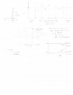
After the holidays I'll be able to perform some experiments on one or two of them. I've a scan I'll attach in the next coupla minutes with some test details and concepts..
Bummer, pencil doesn't come out with enough contrast.
Upper right, just a depiction of twisted pair showing pitch and centroid spacing definitions.
Upper left, a graph of inductance vs coil circumference for close packed single layer wire on a non conductive non magnetic form. In the limit of very large form, there is no inductive shift. As the form becomes smaller, the pitch coupling will alternate between maximum enhancement and maximum cancellation, the growing sine modulation of the inductance. It gets larger as the coil circumference gets smaller because there are more places where the pitches line up.
In the middle is a depiction of a coil of wire, magnetic field lines generated by a solenoidal current, and I've drawn in a cylinder of material to disturb the reluctance path of the field lines. I set a limit of 10 centroid spacing gap between the conductor and the cable to reduce the possibility of coupling to the centroid gap generated dipole field, "near field" disturbances. This test is designed to determine if any solenoidal field is present, as the conductive object will fight time varying flux. A positive change here would indicate that Ed's premise is more likely to have some credence. A negative result here would mean there is no solenoidal field being generated.
Lower right is the bog standard L and R vs frequency relationship.
jn
Attachments
Last edited:
jn, don't hold back, what do you really think?
I think I'll have another drink..
I've a 3 ring binder with 20 sections in it, with various things like the thermal paper I'm (still) working on, changing, embellishing. The scanned page is from that notebook. I'm really annoyed that I've done the entire book in pencil, and it really doesn't scan well...
I decided that I'm not going to simply react to some "net" person tossing bad photo's of bad tests with dialogue along the lines of "here's my proof, you do something to prove me wrong". That's too grade schoolish.
I prefer being a tad more rigorous, as do you.
I am deeply interested in this test aspect, as I'm responsible for proper cabling routing of roughly 250,000 kilometers of multiconductor twisted pair, all with lengths in excess of 100 meters, grouped in bundles of between 30 and 90. External communication between pairs, and from pairs to external aluminum or steel ladder tray and metal conduits from 3/4 to 4.5 inch ID is of significant importance to me and the "customers" I service.
Hope you have a happy holiday Sy.
Regards,
john
ps. on the previous post, when I say "left", I mean my other left...and "right" means my other right.. at least I got top and bottom accurate..
pps. gonna hafta switch to pen.
Last edited:
Bummer, pencil doesn't come out with enough contrast.
Try scanning in greyscale and then do ~80-100% contrast.
How about some examples of the limits? Undamped 5uF, what works and what are the tradeoffs?
5uF trade offs? 80Vpeak, sine, 10 kHz is 5V/us slew rate. Ic = C*dv/dt = 25A --> current protection of many power amps is triggered.
Thats my kind of amps ......
I tried to use paint to contrast it up, didn't find a tool...Try scanning in greyscale and then do ~80-100% contrast.
Happy holidays scott.
jn
ps. got "irfan" to alter the contrast. So, I've put the page in my gallery under the inductance measure album.
Last edited:
For the guys with the proper equipment (there are at least three here).
Settle on a certain cable, measure and exchange notes.
Characteristic Cable Impedance:
http://www.ietlabs.com/pdf/application_notes/035023%207600%20Characteristic%20Cable%20Impedance.pdf
More useful equations and info:
http://www.ietlabs.com/pdf/application_notes/030122%20IET%20LCR%20PRIMER%201st%20Edition.pdf
Merry Christmas
George
Love the links George, thank you. They're just around the corner from me.
I like some of their tech explanations, it's not too highfalutin. I wasn't impressed with their short cal description however, as it'll be inadequate in the low nanohenry range. good for uH and mH, but not nH.
I've been debating whether a 3 terminal guarded technique is better suited for the measurement of cable characteristic inductance, as the cable's shield to conductor capacitance is indeed a confounder. I may have to add that as a test when I do some mike cable tests.
Happy holiday George,
jn
I thought so. JN, you never do the measurements that are needed to prove your position on someone else's measurements.
SY was off by a factor of 5,000, with regards to electrostatic speaker loading. You don't see me attacking him for that, do you?
The problem here is PROOF that we are way off base with the differences that we see in our measurements. You never PROVE our contention wrong, you just challenge our exact measurement procedures and results.
You have done this to Ed Simon, Dr. Hawksford, and me, for example.
No PROOF, just jeering at us that we do not know what how to measure something, even with the best equipment available. And so it goes.
Last edited:
SY was off by a factor of 5,000, with regards to electrostatic speaker loading. You don't seem me attacking him for that, do you?
Go for it. Your "data" (it's data, but you didn't take it) didn't support a thing you were saying.
Wrong, dude. What I do is produce tests and results which are accurate and repeatable.I thought so. JN, you never do the measurements that are needed to prove your position on someone else's measurements.
What I won't do is allow myself to be jerked around by some wannabe on the net, spouting off on some wonderful fiction, doing tests with no understanding or accuracy or repeatability.
You just did.SY was off by a factor of 5,000, with regards to electrostatic speaker loading. You don't see me attacking him for that, do you?
Ed proved his test was off by 3 orders of magnitude, and he did so because he took my advice and measured using the correct setting on his meter. I told him he was off, and why, and how to do it correctly. So, even though Ed proved he was way off by repeating the test correctly, now you expect me to measure a cable correctly to prove that ed was wrong with the first?The problem here is PROOF that we are way off base with the differences that we see in our measurements.
Read the sheet I scanned. That simple page has more theory and test content than anything I'm seeing out of you.
When a test is so poorly done that the data is 3000 times too large, and I challenge it, provide the correct test, theory, and understanding such that Ed can do the test correctly, he does, you now say I didn't prove the test wrong??You never PROVE our contention wrong, you just challenge our exact measurement procedures and results.
Ed was off by three orders of magnitude, I corrected him.You have done this to Ed Simon, Dr. Hawksford, and me, for example.
You went all over the place chasing fairytales when all you had to do was get rid of your testing ground loop,or get a piece of equipment that was properly designed for the test level.
Hawksford wrote a candidate for the journal of irreproduceable results using really bad e/m theory. He was trashed by his peers in academia, some horribly so. I at least explained what he did wrong.
As I said, reading the instruction manual goes a long way. Anybody can buy a piece of test equipment. Getting accurate results seems beyond you. And, if the shoe fits, wear it. Ed did not know how to measure the inductance of a 45 foot piece of cable. You defended him despite his errors..No PROOF, just jeering at us that we do not know what how to measure something, even with the best equipment available.
So much for "practical engineer".
jn
Last edited:
Happy holidays scott.
jn
Same to you and everyone else here.
- Status
- Not open for further replies.
- Home
- Member Areas
- The Lounge
- John Curl's Blowtorch preamplifier part II