R15 should not be inserted, do NOT add a link as this will short the output from the Paradise, just leave the space empty
I think the reason for this is that the soldering of the SMD caps can be tricky and had led to a few solder shorts that proved hard to troubleshoot. Personally I decided to put them in right at the beginning and test for shorts with a meter to be sure there were no issues before going any further.
This is referring to the 10Ohm resistors in the shunt on the main Paradise board (in the PSU section). The shunt is designed to consume around 30mA to work correctly, leaving around 80mA available to the amp. When the Calvin is added the amp now needs around 110mA so the CCS now has insufficient capacity. Changing the 10R resistors to 7R5 increases the CCS current to around 140mA so it can now power the amp and Calvin but still have enough left for itself.
THANK YOU VERY MUCH!
yes, and that is on purpose, these voltages are fine. still, that doesnt explain the offset. Could you try and replace R8a (220 ohm) with a resistor of 560 Ohm?
Replaced 8a with 560R ,now offset is zero. Thanks Alfred.
Quan
Replaced 8a with 560R ,now offset is zero. Thanks Alfred.
Quan
cool, many thanks for the information, glad its working now!
Well, R1+R2 are matched with R8a/b, and if you do the math you see that its possible to get them exactly equal, with the adjustment through the trimpot taking care of the remaining offset. This should work for both positive and negative offset.
Now, imagine the trimpot at zero ohm - the current through the lower half would be much lower (since Q6 has no chance of conducting), and the output voltage would be strongly positive.
My assumption was that - since quan could not remove the offset, even at the extreme position of R8 - that the lower half was not conducting enough. Increasing R8b increases the base-emitter voltage for Q6, so it is conducting more, and the offset can be zeroed. However, this indicates some other imbalance in the circuit......
So this replacement is not necessary for everybody, nor will it change the sound. And, this is the first (of 800 buffers plus my own prototypes) that has this issue, so I am thinking it is not a general problem. Still I am glad we found a quick and proper fix!
Hi,
finally my Paradise is also up and running.
I built small sidecars for (additional) balanced output.
Stephan
I like that, the working PSU, and the 'sidecars' (are you some kind of a computer nerd?
") ). Have fun listening :szp:
). Have fun listening :szp:Hi,
finally my Paradise is also up and running.
I built small sidecars for (additional) balanced output.
Stephan
Great! Hope we get to do that soundcheck one day...
Building Paradise
I was looking at the parts I finally got around to ordering and have a question about R111 and R211. I have the R31 boards. The BOM has 2- 1 ohm resistors but I cant find them on the board. I did the fix of the ground plane on the 330 ohm resistor. I've looked 3-4 times and can't find R111 or R211. That issue and testing and sorting the BC 327 and 337s and I am on my way. Can some one enlighten me? Thank you.
I was looking at the parts I finally got around to ordering and have a question about R111 and R211. I have the R31 boards. The BOM has 2- 1 ohm resistors but I cant find them on the board. I did the fix of the ground plane on the 330 ohm resistor. I've looked 3-4 times and can't find R111 or R211. That issue and testing and sorting the BC 327 and 337s and I am on my way. Can some one enlighten me? Thank you.
Hi Bikerboy,
many thanks for pointing this out. In fact, this was a little fix for the shunt regulator. These two resistors were supposed to go in series with C105 and C205, but finally I did not implement them on the PCB. You will not need these two resistors if the two capacitors are not too "good", meaning the ESR is not too low. You can use regular 10uF caps there, nothing fancy, forget the resistors, and it should be just fine.
So much for checking the documentation multiple times
Hi Bikerboy,
many thanks for pointing this out. In fact, this was a little fix for the shunt regulator. These two resistors were supposed to go in series with C105 and C205, but finally I did not implement them on the PCB. You will not need these two resistors if the two capacitors are not too "good", meaning the ESR is not too low. You can use regular 10uF caps there, nothing fancy, forget the resistors, and it should be just fine.
So much for checking the documentation multiple times
You had me puzzled for a moment (I was checking the PSU schema's for these resistors and could not find them
they are fatamorsistors I think/thought) (when I tried to answer bikerboy ) In the end it is the cheap/expensive and low/high-quality discussion for Cx05. It is all my fault, I did say at some point cheap-low-quality-capacitor, where I should have said; use a 'standard' capacitor, not one with an extremely low ESR (maybe this helps, and maybe more confusion has been created).These are the most important/relevant messages regarding PSU and Pre-Reg.
- Mpp #4375 PSU-pre-regulator.
- Mpp #4610 V2 Schemas UPS and Amp.
- Mpp #6506 CCS fine-tuning.
- Mpp #6462 PSU with my notes.
- Mpp #6809 Do not try to feed the CVS of the CCS of the shunt with a regulated power supply.
- Mpp #7127 More about transformer selection.
- Mpp #7635 Single and dual transformer wiring (also corrected drawing) (See also #7733).
- Mpp #7733 Grounding (PSU, RIAA and Player).
- Mpp #7810 35V PSU for the CroMagnon.
- Mpp #7830 The PSU explained.
- Mpp #8386 My resistor recommendation’s.
- My Paradise #56 PSU Noise.
- Masterpiece #951 That's not a PSRR test (it's a CIR test)
- PradiseBuilders #13 Schema's and assembly guide.
- PradiseBuilders #155 Vdc input voltage minimum simulated.
- PradiseBuilders #970 PSU oscillates; posible solutions?
- PradiseBuilders #983 Compensating the PSU for oscillations.
- PradiseBuilders #1173 Fixing oscillations (up to #1182).
- PradiseBuilders #1322 Fuse .
- PradiseBuilders #1387 Updated Paradise R3 assembly guide (Also German).
- PradiseBuilders #1403 Capacitors bad vs good.
- PradiseBuilders #1593 PSU Power Transistor selection.
- PradiseBuilders #1644 PSU Output Impedance.
- PradiseBuilders #1680 PSU Power Supply Suppression Ratio(PSSR).
- PradiseBuilders #1772 NJF selection for the PSU.
- PradiseBuilders #1887 Empirical NJF Rgs determination.
- PradiseBuilders #2127 More about the PSU fets (J113's etc).
- PradiseBuilders #2969 About the Paradise PSU using Calvin buffers.
- PradiseBuilders #3134 More ESR confusion .
Last edited:
Hi All
A quick build update.
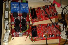
I fired up the Paradise/Calvin boards today and very roughly set the IP offset with a 10K load and well I never. No magic smoke released but a large +/-125MV offset on both boards.
The Calvin adjusts down to 0V between IP and OP so looking good voltage wise.
Ok I remember Paulski’s remarks re boxing and flipped the lid on and let it warm up for 15mins or so.
The OP offset dropped like a stone with the lid on so worth keeping in mind when you first measure.
I now have a more manageable +/- 7mv on both boards OP but I’d like it a little lower.
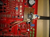
So I think I’ll be trying to thermocouple the front end transistors to see if that helps.
The 7mv seems to be OK but every little helps.
some not very good pictures of my build so far


A quick build update.
I fired up the Paradise/Calvin boards today and very roughly set the IP offset with a 10K load and well I never. No magic smoke released but a large +/-125MV offset on both boards.
The Calvin adjusts down to 0V between IP and OP so looking good voltage wise.
Ok I remember Paulski’s remarks re boxing and flipped the lid on and let it warm up for 15mins or so.
The OP offset dropped like a stone with the lid on so worth keeping in mind when you first measure.
I now have a more manageable +/- 7mv on both boards OP but I’d like it a little lower.
So I think I’ll be trying to thermocouple the front end transistors to see if that helps.
The 7mv seems to be OK but every little helps.
some not very good pictures of my build so far
Hi All...
some not very good pictures of my build so far...
Looks great, now go and listen to it
Hi Guys
Thanks for the nice comments
I’ve attached some copper sheet to the front end transistors today so over night for the thermal epoxy to set. Then a few days switched on and off just to make sure that all is well.
Just to say that this has been a pretty challenging build for me and one that I would not have started if not for all of the fantastic contributions on this thread.
They all helped immensely.
I’ll post tommorow with an offset update with the copper in place.
Next testing and then listening can begin if all is well.
- Home
- Source & Line
- Analogue Source
- Paradise Builders