Hi james watt,
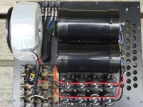
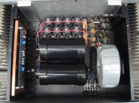
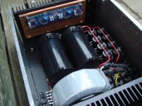
- PSUs are 2 x (625VA 18VAC + 2 x [44uF-0R094-44uF] CRCs)
- MOSFETs 2SJ201 / 2SK1530, relatively well matched, each biased at 1,085A.
- Offset voltage adjusted to below +-1mV on the bench, each channel separately stand-alone. After unpowering, cooling down, power up (and heating up to stable 62C) again below +-3mV [several cycles performed]. For allowing more precise tuning the offset I added some more resistors in parallel with the potentiometers. It was still a long and exhausting process (EUVL Floating X topology - all 4 quadrants have to be aligned). Now, with complete amp mounted I guess I will have to readjust the offset some time. But, as it already sounds so good, this can wait…
The rest + PCB layout can be found in this post. Some layout improvements before manufacturing were done, but most changes in schematic only (source resistors 0R235, several other component values optimized).
Gain is about 20dB.
-- xLoff
Formidable, xLoff!
It seems your impressive engineering efforts leads to a very satisfying result.
+-3mV offset is nothing!
I am happy to be able to bring my aleph-X below 100mV.
How many Mosfets did you purchase /measure to find the matched pairs?
I assume you dont use 4ohm speakers at concert level in order to keep the peek output current below the Mosfet spec?
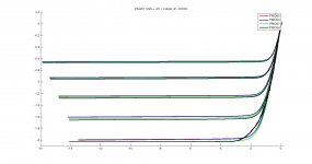
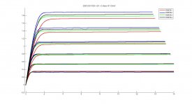
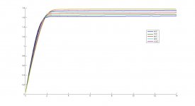
I bought the 4 pairs from zhoufang, already matched. See attached IV-curves (please keep in mind I have used post processing - curve fitting on 1024 data points).
The Safe Operating Area (SOA) in my case would rather be limited by the level just before the neighbors brake though the door / call the police...
-- xLoff
The Safe Operating Area (SOA) in my case would rather be limited by the level just before the neighbors brake though the door / call the police...
-- xLoff
Attachments
No, It was in June. But now it seems like he has a new, good stock of his "Toshiba 2SK1530 2SJ201 Precision Matched to 0.01V" sets. I was considering doing a version with 3 output pairs in each quadrant (F5T-X / Balanced). Luckily I could not get the FETs... Now I see I don't need that amp.............yet (but we don't DIY because of need, do we? ") )
)
-- xLoff
)-- xLoff
I never tried sending him any emails. He has some negative comments on this topic on his ebay profile though. I think I had to wait quite a while for the FETs to be shipped out of Singapore to Europe, ~4 weeks if I remember correctly.
-- xLoff
Would you mind sharing his EBay link? Thanks
Regards,
F5 monos' part build
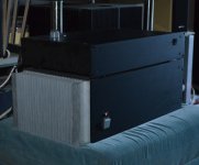
This project is currently parked! till the new year. The heat sinks/front/and rear panels are loose fit.
This project is currently parked! till the new year. The heat sinks/front/and rear panels are loose fit.
Attachments
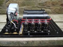
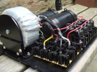
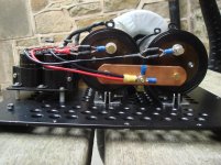
Esprit: As they are monoblocks, will you be running output transistors to both heat sinks? Or...?
Both of the output transistors will be co located at the PCB, the copper plate is there in the interest of mass and spreading heat. They are L/Right hand, which caused me a bit of head scratching during assembly!. The 12mm front panel will be securely attached to both heat sinks. IF there is too much heat sink some metal can always be isolated,

IF there is too much heat sink some metal can always be isolated,
Never heard of too much heat sink, as one is tempted to keep turning up the bias further and further...
ACA - Burning Amp, almost done. I could use input
All,
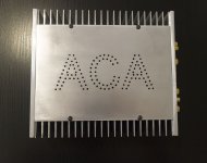
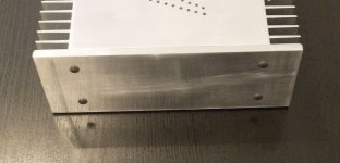
Attached are my ACA pics. I hadn't thought abut building an ACA, I'm in the middle of a J2 clone and I have SIT parts sitting on the shelf. The change of heart came at this year's BA Festival. I won an ACA kit in the raffle! I've never won any contest, never mind a Pass amp!
I usually like to design and etch my own PCBs. In this case, the kit provided them, so I would have to add the DIY touch in another way. The chassis was the obvious choice. I have never built my own chassis, as I only own hand tools, and I want my Class A amps to be made of metal (for safety), so thought was in order.
Off I went to SF scrap metal, and bought some salvage aluminum buss bar for $1/lbs.
Next I bought a Bosch Jig Saw (awesomeness) and cut my aluminum pieces to size. Cutting aluminum with the Bosch was a breeze. I'd never cut metal before, and I was worried about safely and accuracy, but the Bosch is highly recommended.
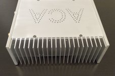
Some elbow grease and bastard files later, and I was ready to put the box together. The ACA logo was hand done on the drillpress, boy I wish I had a CNC mill...
I decided on M4 screws (I had a bunch left over from my XF5 project), drilled and tapped my heatsinks (part of the kit), and the chassis was born.
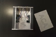
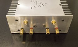
The next issue was tough for me, many of the parts were meant for a thin sheet metal chassis, and I would have to mill out some of the thickness to use them - this was especially true of the power connectors.
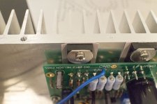
I had a 1/2" end mill from a speaker project, I mounted in my $30 Harborfreight drill press, using oil and going slowly, and I got lucky (see pictures). I also had to file down the FET washers to let the top sit correctly (see pictures).
Left to be done - the power switch. I don't have a drill bit large enough to mount the powerswitch supplied, and I would also have to mill metal away to make it stay in place. I'm seeking a nice, mountable with a drill press, power switch. I'd been thinking about the momentary switch solution here:
The ε24 Power Switch Driver Circuit
I was also thinking about a capacitive touch switch for the chassis itself, but I am concerned about a touch switch going rogue in the case of a Class A chassis with the heat involved.
Suggestions are welcome. I would also welcome anyone doing anodizing in the Bay Area.
All,
Attached are my ACA pics. I hadn't thought abut building an ACA, I'm in the middle of a J2 clone and I have SIT parts sitting on the shelf. The change of heart came at this year's BA Festival. I won an ACA kit in the raffle! I've never won any contest, never mind a Pass amp!
I usually like to design and etch my own PCBs. In this case, the kit provided them, so I would have to add the DIY touch in another way. The chassis was the obvious choice. I have never built my own chassis, as I only own hand tools, and I want my Class A amps to be made of metal (for safety), so thought was in order.
Off I went to SF scrap metal, and bought some salvage aluminum buss bar for $1/lbs.
Next I bought a Bosch Jig Saw (awesomeness) and cut my aluminum pieces to size. Cutting aluminum with the Bosch was a breeze. I'd never cut metal before, and I was worried about safely and accuracy, but the Bosch is highly recommended.
Some elbow grease and bastard files later, and I was ready to put the box together. The ACA logo was hand done on the drillpress, boy I wish I had a CNC mill...
I decided on M4 screws (I had a bunch left over from my XF5 project), drilled and tapped my heatsinks (part of the kit), and the chassis was born.
The next issue was tough for me, many of the parts were meant for a thin sheet metal chassis, and I would have to mill out some of the thickness to use them - this was especially true of the power connectors.
I had a 1/2" end mill from a speaker project, I mounted in my $30 Harborfreight drill press, using oil and going slowly, and I got lucky (see pictures). I also had to file down the FET washers to let the top sit correctly (see pictures).
Left to be done - the power switch. I don't have a drill bit large enough to mount the powerswitch supplied, and I would also have to mill metal away to make it stay in place. I'm seeking a nice, mountable with a drill press, power switch. I'd been thinking about the momentary switch solution here:
The ε24 Power Switch Driver Circuit
I was also thinking about a capacitive touch switch for the chassis itself, but I am concerned about a touch switch going rogue in the case of a Class A chassis with the heat involved.
Suggestions are welcome. I would also welcome anyone doing anodizing in the Bay Area.
Attachments
Last edited:
- Home
- Amplifiers
- Pass Labs
- Pictures of your diy Pass amplifier