Hi there !
Today I had a speaker test for a friend at a new shop in town. We wanted to use his gear to move the speakers:
the TK2050 Class D amp I've done for him, 30/50W (hard to tell, depends on speaker's Z),
and the CD53 I've modded http://atsh.free.fr/MarantzCDx3/10MecaRegulee.jpg (now has a dedicated PSU for drivers).
Well it was a good time to listen to what it is worth.
Sadly the amp was too short in power. Not the best candidate for the speakers tested, a very bad performer on some top speakers.
... and the good old CD53? Well, the seller never asked to change it for better, and after trying combo of speakers/amps, we finally asked him if a better one was needed. No, because better is... at least a Marantz SA something at 2500€ (guess it's the new SA-14S1... don't remeber) !
It is worth modding, defo. And this is not a super modded one, look: a reused TX, some lost coax, a GDAudio "twin" reclock, salt with some LM317, few good caps, a non CFPed DOS, cheap MKP and voilà!
As for the amp seems power is power when it's a room of 50m2 to fill....
Last edited:
Hi Matthieu,
Nice work! Good to hear your player performed so well. Proves again that a little tweaking can lift these players to a whole new level")
SA-14 eh? Must have missed that one. I'd still like to get my hands on an SA11-S2 to give it a good make-over. I'm hoping to find a used one at a decent price, the new ones are still > € 2500,- over here.
Ray
Nice work! Good to hear your player performed so well. Proves again that a little tweaking can lift these players to a whole new level
SA-14 eh? Must have missed that one. I'd still like to get my hands on an SA11-S2 to give it a good make-over. I'm hoping to find a used one at a decent price, the new ones are still > € 2500,- over here.
Ray
bessel curve
Tried this much better than before spot on with the values ray need a dos
thx alan
Check this PDF.
The second schematic and graph shows the Bessel curve.
The ideal values are a 430pF cap and 14k resistors. The inductor has to be changed to 470uH to keep the notch filter tuned to the correct frequency.
Ray
Tried this much better than before spot on with the values ray
need a dos thx alan
Two Fleas
Hi
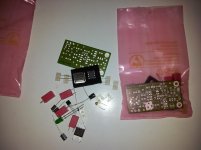
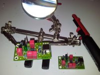
Received two Fleas for DAC and Servo, from Ray few days ago. Have been putting them together and mounting in the player. SMD soldering is pretty tricky for a guy with a bad eyesight, but I pulled it off using magnifying glass and a lamp.
Sound is now very smooth and detailed. I expect it to get even better with more run-in time.
I want to thank Ray for good service and quick delivery!
Hi
Received two Fleas for DAC and Servo, from Ray few days ago. Have been putting them together and mounting in the player. SMD soldering is pretty tricky for a guy with a bad eyesight, but I pulled it off using magnifying glass and a lamp.
Sound is now very smooth and detailed. I expect it to get even better with more run-in time.
I want to thank Ray for good service and quick delivery!
Attachments
Looks nice. I've finished mine about a week ago,but haven't put it in yet.
Could you upload a picture of all of your connections on the flea and the board?
Sorry, I don't have pictures of that and I have put my player back together.
For DAC: remove the crystal, CD02 and CD03 - use the holes left by the CD03. Looking at the front of the player, connect ground output of the Flea to the RIGHT hole and the signal output of the Flea to the other hole.
For Servo: remove the resonator (X101) and R126. Use the MIDDLE hole left by the resonator for the ground output of the Flea. Looking at the front of the player, use the RIGHT hole of R126 for the signal output of the Flea.
It's best to use separate PSU for the Fleas. If you don't have separate PSU, you can take 20v feed from C803 in the player.
I want to thank Ray for good service and quick delivery!
You're welcome!
Nice work, good to hear you like the result.
Ray
Hi guys,
My laser is getting bad again (skipping tracks). I tried to turn the trimpot at the bottom of the disc pcb, but that didn't do enough. Last time I put in a laser from a Philips CD713. This lasted for a year or so. Maybe I'm better off getting a new laser mechanism from ebay, but I've read some are not very good. Any suggestion for finding a good one?
Regards,
Bart
That's always difficult. Don't have the illusion that some of them are 'original Philips' and some are not, because they are all the same: made in China.
I usually get the complete mechanism assembly with the disc and sled motors, that will be around 15 bucks. It happened a few times that one didn't work, in most cases you get a new replacement for free.
Ray
I usually get the complete mechanism assembly with the disc and sled motors, that will be around 15 bucks. It happened a few times that one didn't work, in most cases you get a new replacement for free.
Ray
If you are definitely going to replace the laser then you might want to attempt a strip-down and clean as detailed here....
http://www.diyaudio.com/forums/digital-source/118902-stripdown-clean-cdm12-4-a.html
http://www.diyaudio.com/forums/digital-source/118902-stripdown-clean-cdm12-4-a.html
HI Guys,
I have a cd63KI and wish to do the 3 TX upgrade.
I have a couple of questions after reading Highlanders post on page 1853.
"Ben has kindly confirmed that the wiring for the 3 Transformers are correct, i.e:
U305 - 12V in from 5VA Tx
U306 - 18V in from 15VA Tx
U307 - 18V in from 15VA Tx
U308 - 12V in from 50VA Tx
U309 - Ground for the 3 Tx
U310 - 12V in from 50VA Tx
U311 - 12V in from 5VA TX
U312 - 12V in after passing through the 16.4ohm resistor."
At U312, what feeds it and why the 16.4 ohm resister. 3tx's = 6 secondaries and 7 supplies to service!
I have 15v Spower regs on the analogue rails, so will the 18v supply be ok.
Also, i'd like to add 2x Spower's the decoder.
Dac and Servo done already ( Brents work)
Enough questions for now me thinks.
cheers guys
I can tell you that the resistor is to lower the voltage as the original voltage supplying U312 was only 3.4 volts. 16.4 ohms though may not be high enough. Regarding your other questions you will have to wait for someone else to respond as I myself have not yet got around to replacing the transformer.
In my experience 16.4 ohm is insufficient to drop the voltage down and I used 47 ohm instead.At U312, what feeds it and why the 16.4 ohm resister. 3tx's = 6 secondaries and 7 supplies to service!
I have 15v Spower regs on the analogue rails, so will the 18v supply be ok.
I also used 15V low voltage regulators for the opamps and IMHO it should be better than using 12V. I can confirm that 18V supply to the input of the 15V regulator is OK.
You may refer to my thread in #19290 about how I have constructed my 3 TXs. A circuit diagram is also included in that thread.
http://www.diyaudio.com/forums/digital-source/54009-marantz-cd63-cd67-mods-list-1929.html
Last edited:
3 TX upgrade
Ok guys I understand now. Thanks
For the Decoder, am I correct thinking the 5v feed comes from R508, R511. Going to drop some Spowers in there
With that work done the player will be where I want it.
cheers
In my experience 16.4 ohm is insufficient to drop the voltage down and I used 47 ohm instead.
I also used 15V low voltage regulators for the opamps and IMHO it should be better than using 12V. I can confirm that 18V supply to the input of the 15V regulator is OK.
You may refer to my thread in #19290 about how I have constructed my 3 TXs. A circuit diagram is also included in that thread.
http://www.diyaudio.com/forums/digital-source/54009-marantz-cd63-cd67-mods-list-1929.html
Ok guys I understand now. Thanks
For the Decoder, am I correct thinking the 5v feed comes from R508, R511. Going to drop some Spowers in there
With that work done the player will be where I want it.
cheers
Last edited:
Ok guys I understand now. Thanks
For the Decoder, am I correct thinking the 5v feed comes from R508, R511. Going to drop some Spowers in there
With that work done the player will be where I want it.
cheers
Right. First disconnect the original +5V supply from Q811 to R508 and R511. Install two Spowers and feed the regulated +5V after R508 and R511. Job done
- Home
- Source & Line
- Digital Source
- Marantz CD63 & CD67 mods list