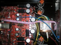
I am confused because it did not work and then everything worked an now it do not. When turning the dac off and on the display change without any reason from time to time depending how long it have been turned off. Buttons do not work and remote not either.
When it worked it had been turned off for some hours.
Maybee to much capacitors on the supplys ?
When it worked it had been turned off for some hours.
Maybee to much capacitors on the supplys ?
Hi Erlend Sæterdal!
you use code for stand by ??
If you sue big cap, it is not good for the sound! please remove it!
ok, i will sent all information for the mode, it is easy if you like it!
thanks
I do not know what Code for standby means. After 4 hours turned off almost everything works. Only the Coax could not been turned on.
I wonder if it is because off bad connection to the board when burning. No gnd so the voltage came only from the other cables. I will solder a seperate thick gnd cable from LCD board to main board.
I do not agree about sound and caps .
Everything worked and I turned it off took out the I/V jumpers. The little Dc on output was gone but remote and buttons on front does not work anymore. Must be the moon ?
no, lcd backlight ?
Is there a cable from DAC module to controller ?
Could you send a photo of the DAC module and controller ?
When turning off and quick on there is no light. Measured the gnd connection before and after soldering extra gnd cable 0,9 and 0,2 ohm. Wonder if the other lines from board to LCD board is bad to.
Picture tomorrow maybe or later this day.
LCD brightness can be? or dark??
No I have adjusted that. I will change the Black Gate cap for 3,3 digital to something else tonight. Anyway I do not like the LCD to use same supply as for the digital.
So!
What happened to your DAC?
What can I help? Tell me more!
Thank you
When turned off for 4 or 5 hours everything works for the first minute. When turned off and on again quickly the display do not light at all.
I will take display board out tonight and resolder everything.
ok. but i will sent Other LCD and PCB to you!
waiter it!~
thanks
Quanghao, you have a message!
I SEN TO YOU I WRITE LOW LOW VALUE!
please not worry it!
After receiving the final version of DAC modules we have detected a very little oscillations on shunt regulators in high frequency range (about 150KHz).
Measurements and simulations made with the collaboration of CAAD allowed to find a simple solution to this problem.
To make this modifications are not necessarily required SMD components but if you want to use SMD and you have problems to find these components you can ask to Quang Hào.
1) Remove R9 on op-amp modules (as suggested before)
2) Remove R10 on op-amp modules (as suggested before)
The following modification must only be made only on +1.2V , +3,3V and +15V shunt regulators.
3) Add 100n X7R as described on attached pic -->All are X7R (better dialectric compared to U5r , Z5R etc)
4) Add 1uF X7R as described on attached pic -->All are X7R (better dialectric compared to U5r , Z5R etc)
These modifications also will reduce the temperature on the shunt of the op-amp module.
The modification as been applied on the last DAC modules sent.
See the image created by CAAD.
Hi Audiodesign,
4) add 1uF X7R on the pin 1-2 OPA2134 (DAC and on op-amp modules)
3) add 0.1uF X7R on pin ? Dac and on op-amp ?
Thanks!
ok. but i will sent Other LCD and PCB to you!
waiter it!~
thanks
Well I resoldered the LCD board. The big chip I was not able to solder.
It did not help at all. Same problem exists still.
I have planned to bring this dac for the hifi Club in Copenhagen in friday in 2 weeks. That I can not.
Please send a new one so soon as possible thank you very much.
No I have adjusted that. I will change the Black Gate cap for 3,3 digital to something else tonight. Anyway I do not like the LCD to use same supply as for the digital.
The LCD have a separated regulator, it is not the same of the digital
Hi Audiodesign,
4) add 1uF X7R on the pin 1-2 OPA2134 (DAC and on op-amp modules)
3) add 0.1uF X7R on pin ? Dac and on op-amp ?
Thanks!
0.1uF pin 6-7 OPA2134 (DAC and on op-amp modules)
- Status
- This old topic is closed. If you want to reopen this topic, contact a moderator using the "Report Post" button.
- Home
- More Vendors...
- Quanghao Audio Design
- DAC-END R (ES9018) full assembled board
