Hi Terry,
Do you match the transistor?
I only use hFE tester from my DMM to match them,
result not so close match
but it is better than not.
The hFE test also tell us that they are still in good condition.
Cause I play too much with my PeeCeeBee, I also burn some 10 ohm resistor & BD139-140 also dead...
Next I want to try other way how to matching transistor
& the offset will be better/easier to set.
Also it is good idea to match 2k2 // 100 ohm resistor
I did match all the resistors, only few resistor to match won't hurt you")
When first time I also have dificulty to measure offset, I got oscillation there.
I put 33pF capacitor on each base to collector VAS transistor & they do the job.
Regards
John
Do you match the transistor?
I only use hFE tester from my DMM to match them,
result not so close match
but it is better than not.
The hFE test also tell us that they are still in good condition.
Cause I play too much with my PeeCeeBee, I also burn some 10 ohm resistor & BD139-140 also dead...
Next I want to try other way how to matching transistor
& the offset will be better/easier to set.
Also it is good idea to match 2k2 // 100 ohm resistor
I did match all the resistors, only few resistor to match won't hurt you
When first time I also have dificulty to measure offset, I got oscillation there.
I put 33pF capacitor on each base to collector VAS transistor & they do the job.
Regards
John
Hi Terry,
Do you match the transistor?
I only use hFE tester from my DMM to match them,
result not so close match
but it is better than not.
The hFE test also tell us that they are still in good condition.
Cause I play too much with my PeeCeeBee, I also burn some 10 ohm resistor & BD139-140 also dead...
Next I want to try other way how to matching transistor
& the offset will be better/easier to set.
Also it is good idea to match 2k2 // 100 ohm resistor
I did match all the resistors, only few resistor to match won't hurt you
When first time I also have dificulty to measure offset, I got oscillation there.
I put 33pF capacitor on each base to collector VAS transistor & they do the job.
Regards
John
Hi john,
I ask LC about match on TSSA topic. He answer me that DMM matching is sufficient as error will affect same all mesures since we don't use mesure to futher calculation just to compare transistors. With hi speed VAS transistors cap compensation is really important i think as many source can give osscillations...
Marc
This is true, but not the whole story.Hi john,
I ask LC about match on TSSA topic. He answer me that DMM matching is sufficient as error will affect same all mesures...
The hfe curves for PNP and NPN devices are different. So, although it is true that if both measurements are off by the same percentage, the result is still a match, but ONLY at the single point where the DMM has set the current.
So, if the DMM measures hfe at some arbitrarily low current, a complementary pair will NOT be matched if the actual (in-circuit) current is much higher (tested).
So, although using a DMM is better than nothing at all, one should not assume that a single point match at a very low current means you have a true complementary pair.
Unfortunately, at least in this thread, we do not really know what kind of distortion results from hfe differences in the case of this circuit. A simulation might show that, if the models were adjusted carefully (not sure though).
Example:
KSC3503E/KSA1381E , heatsinked, tested as random pairs
(The KSC3503E is old stock, the KSA1381E is new, from Mouser)
(pair 1, good match)
12mA:
hfe: 190/172 (10%)
Vbe: .645/.652
Vce: ~27V
18mA:
hfe: 205/193(6%)
Vbe: .620/.623
Vce: ~37V
(pair 2, fair-to-poor match)
12mA:
hfe: 192/160 (20%)
Vbe: .637/.645
18mA:
hfe: 200/172 (16%)
Vbe: .629/.634
You can see from the underlined numbers that as the current goes up, the difference in hfe gets smaller. Eventually, the hfe curves will intersect, and the devices will have the same gain, but this will happen well above the intended bias current.
By contrast, if one were to measure at a very low current, the difference in gain would seem very large...
I think there is no simple solution to this hFE problem of the active devices, other than buying a bunch and taking Vbe vs Ic vs Vce curves of each and then compare graphically... super-tech-fool-proof-0%THD.
That said, is there any audibly tremendous advantage of matching them to that degree? IMO, perfect matching won't contribute significantly to the Slew Rate of this amp, one of the main characteristic that affects perception almost equally to everyone. It's already close to perfect(audibly) and I have given up on thinking how to reduce THD "even" further. Some simple and well-known tricks can be applied to achieve desired THD while still not demanding a scope or supermatch pairs and/or five DMMs.
That said, is there any audibly tremendous advantage of matching them to that degree? IMO, perfect matching won't contribute significantly to the Slew Rate of this amp, one of the main characteristic that affects perception almost equally to everyone. It's already close to perfect(audibly) and I have given up on thinking how to reduce THD "even" further. Some simple and well-known tricks can be applied to achieve desired THD while still not demanding a scope or supermatch pairs and/or five DMMs.
Thanks. I am definitely NOT advocating some kind of super-elaborate (and expensive) matching. Not at all. Just trying to say that a pair matched using a DMM will probably not match to the same degree in-circuit. My post was intended to show that, but I was not clear in that regard, sorry.I think there is no simple solution to this hFE problem of the active devices, other than buying a bunch and taking Vbe vs Ic vs Vce curves of each and then compare graphically... super-tech-fool-proof-0%THD.
No No NO!
I am not saying you are doing that! Your message is clear to me.
I was just saying that because true-matching is near-impossible, so it should not be taken extremely seriously, that's all.
I'm sorry if my words seemed offensive. I didn't have any such intention.

I am not saying you are doing that! Your message is clear to me.
I was just saying that because true-matching is near-impossible, so it should not be taken extremely seriously, that's all.
I'm sorry if my words seemed offensive. I didn't have any such intention.

Not at all Shaan, thanks for the good thoughts,No No NO!
I am not saying you are doing that! Your message is clear to me.
I was just saying that because true-matching is near-impossible, so it should not be taken extremely seriously, that's all.
I'm sorry if my words seemed offensive. I didn't have any such intention.

Hi
Try 100mA for thermal indifference
http://www.jaycar.com.au/images_uploaded/2SK10568.PDF. page 4
Do you finish the double push ?
What si the bias for the double push ?
Thanks
Try 100mA for thermal indifference
http://www.jaycar.com.au/images_uploaded/2SK10568.PDF. page 4
Do you finish the double push ?
What si the bias for the double push ?
Thanks
Last edited:
Update on my breadboard peeceebee.
I bought 0.1% resistors, ripped up the wiring and re-wired with 0.1% resistors per the schematic on page 1 of this thread.
My voltage is +/-30 as that is the max of my adjustable bench power supplies.
Current readings, 2mA , 13mA, 165 mA.
Offset is - a few mV cold and quickly goes to 0 and then when everything is warm about + 9 mV.
No heat sink on the Vas, Small heat sink on output FETs.
I used exact-matched transistors. KSA992/1845 on the input. KSC3503E/1381E for the VAS. Matching at 30V at in-circuit bias current.
When I build on a PCB I will heat sink the VAS transistors.
No tweak needed for offset. I was very pleased.
Here is a question. From a transistor rating standpoint there is nothing preventing me from using +/- 55V supplies and adjusting the bias set resistors. Has anyone used higher voltage for a peeceebee?
Hi Shaan,Hi guys.
My third board is now shakin' the sub... As smooth as ever...
Bias is very low than the two satellite drivers, about 4mA in the VAS and 70mA in the FETs, PS is +/-35V, load is my old faithful 4ohm spherical sub.
Will show the pix tomorrow...
I'm waiting the picx...
I also got them shakin the sub's
I was connect the single pair output to 8 ohm sub, I see how the cone move...
bias also lower & PS is +/-32V input caps 4,7uF I though I must lower the input caps.
I don't like to see the sub's cone move like that...
My friend seems not believe me, the sound is so loud with only very tinny transformer
Hi Woofertester,Update on my breadboard peeceebee.
I bought 0.1% resistors, ripped up the wiring and re-wired with 0.1% resistors per the schematic on page 1 of this thread.
....
Here is a question. From a transistor rating standpoint there is nothing preventing me from using +/- 55V supplies and adjusting the bias set resistors. Has anyone used higher voltage for a peeceebee?
I'm also will try higher voltage too, but I only do that after my "double barrel gun" finished
For single pair output I guess +/-45V is max voltage, even lower voltage just sound so loud
Last edited:
Here is a question. From a transistor rating standpoint there is nothing preventing me from using +/- 55V supplies and adjusting the bias set resistors. Has anyone used higher voltage for a peeceebee?
It's nice see if the increase in voltage rails translates to an increase in power of the PeeCeeBee and it is possibly safe to push for higher voltage because looking at the SOA of FET, it is capable of 100 watt power, say for for example 2 ampere at 50 volts.
Hi
Try 100mA for thermal indifference
http://www.jaycar.com.au/images_uploaded/2SK10568.PDF. page 4
Do you finish the double push ?
What si the bias for the double push ?
Thanks
Hi Cuda.
Keep the bias between 150mA and 200mA per FET for best distortion performance and to activate negative temperature co-efficient in the O/P stage.
Update on my breadboard peeceebee.
I bought 0.1% resistors, ripped up the wiring and re-wired with 0.1% resistors per the schematic on page 1 of this thread.
My voltage is +/-30 as that is the max of my adjustable bench power supplies.
Current readings, 2mA , 13mA, 165 mA.
Offset is - a few mV cold and quickly goes to 0 and then when everything is warm about + 9 mV.
No heat sink on the Vas, Small heat sink on output FETs.
I used exact-matched transistors. KSA992/1845 on the input. KSC3503E/1381E for the VAS. Matching at 30V at in-circuit bias current.
When I build on a PCB I will heat sink the VAS transistors.
No tweak needed for offset. I was very pleased.
Pleased to know you like the simple setup. How are the waves from the speakers?
Here is a question. From a transistor rating standpoint there is nothing preventing me from using +/- 55V supplies and adjusting the bias set resistors. Has anyone used higher voltage for a peeceebee?
AFAIK, none has run a PeeCeeBee at +/-55V. But with the devices you are using, it seems to me to be perfectly doable. Update us with pix and details of your high power setup.
Just one thing, at higher voltage it's best to use multiple FETs than a single one, coz available current is low at high voltage due to SOA limitation and something bad might happen if speaker impedance dips too low. Ultimately it's the current that drives the coil.
Hi Shaan,
I'm waiting the picx...
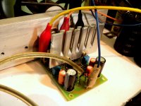
Here they are...
VAS transistors share the same heat sink, current source is the default 15K, offset 20mV default. In final setup main heat sink will be way larger than the one currently used with fan cooling.
Attachments
This is truly a great design to DIY. I will post pics when there is something new.
I moved the feedback point from the output to the top of a grounded shunt to see how using the VSSA as a current source will work. The offset changed to a large 100mV reading. I am thinking of how to balance the offset and retain the current source output.
I am building this to drive speakers for testing. The monster 12" on my bench is 12 ohms at Fs. It can take 4A RMS with no difficulty. I think Xmax happens at 5A but I have no amp that can produce 5A into 12 ohms.
Interesting idea. I feel I should try this too... hmm... VSSA as a current source, with source follower outputs... lot's of current to source...
I remember the sound of a high output impedance amp was totally different from that of a voltage source. Built one with the national LM4701 chip. I liked the mid and treble very much.
I remember the sound of a high output impedance amp was totally different from that of a voltage source. Built one with the national LM4701 chip. I liked the mid and treble very much.
Interesting idea. I feel I should try this too... hmm... VSSA as a current source, with source follower outputs... lot's of current to source...
I remember the sound of a high output impedance amp was totally different from that of a voltage source. Built one with the national LM4701 chip. I liked the mid and treble very much.
One thought is to increase the feedback resistors from 2.2k to 220k and then use 2.2k feedback resistors from the shunt to the input with a capacitor in series.
This would create separate AC and DC feedback paths.
The sub must be better than my pipe's one,Here they are...
VAS transistors share the same heat sink, current source is the default 15K, offset 20mV default. In final setup main heat sink will be way larger than the one currently used with fan cooling.
I think I should make something like it too
so I have 2.1 setup too...
How about the sound,
with your PeeCeeBee any speaker will be shackin'
& can show their potential
people around will amazed with the sound produced
Some time before I was doubt the low response, I guess not so "deep bass"
I did add a buffer & I was surprise...
The standard PeeCeeBee is so good, so loud.
I've made small changes, now the VAS(BD139-140) has their own heatsink.
Some parts under the boards & bias is reduced(changed 15k to 18k resistor)...
Add few caps too
The double barel gun will slowly build
Now I guess another the 200 watter's amp I was build need to sell
or some repair
Last edited:
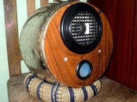
Hi John.
Nobody can beat your pipe speakers, most innovative DIY enclosure I will say.
Yes the sub has superb bass with PeeCeeBee, and cone control is just excellent, better than any amp I previously tried on the sub. It's just a 4 inch little guy, but trust me the kicks and basses seem like 40 inch hehe.
I played Akon's 'I wanna love you' some days ago, to see how it manages with the track, it did better than I expected. All the doors and windows were shaking with it, it was fun.
I guess the sub, with the particular driver and port, is at optimum tuning. Although I didn't do any mathwork/calculation of any kind before making it. Just put it all together and eventually dug up some hidden treasure.
I have plan to build another, with a little bigger enclosure and driver than this one.
Happy listening.
Dimensions: 5" x 2.5" (127mm x 63.5mm)
Have fun.


...
..
.

Hi, do you have more information, spec for this amp ?
final schematic
dissipation
bias
power supply needed (VA, caps)
BOM
Thanks
- Home
- Amplifiers
- Solid State
- PeeCeeBee