3D view Shaan #1
Hi Shaan & everyone...
I'm sorry for my off topic question
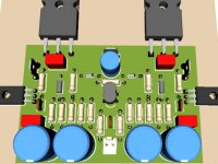
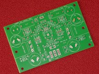
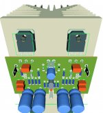
Here my 3D PeeCeeCee , comment are very welcome
based on schematic post #1 & I only remove 10uF at input
Regards
Hi Naf,
I guess we can use K170 as CCS, but for sure wait for others says...
I'm still gathering parts, not complete yet
Already have hfe = 600+ for NPN input tr but no PNP.
Hi Shaan & everyone...
I'm sorry for my off topic question
No problem as long as the peeceebee philosophy is maintained, i.e. 1)all through hole parts, 2)single layer layout and 3)no CCS.
shaan
Here my 3D PeeCeeCee
, comment are very welcome based on schematic post #1 & I only remove 10uF at input
Regards
Attachments
First channel built and tested...
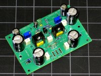
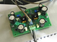
First one of my boards built and tested this weekend, and now playing music!
(or singing, as Shaan would say)
No fireworks or smoke, offset adjusts to zero, bias settles pretty much as described in other posts above. Heat sinks stay cool, no excess heat that might indicate instability or oscillation.
Very easy to build and test (the hard work being already done by Lazy Cat and Shaan), so if anyone else is sitting on the fence, consider yourself encouraged... Only reason it took so long to get from layout to this point is being out of town.
I am testing the first board with pretty conventional components which are easily available, no long lead times, no "Un-obtainium", nothing expensive, and no audiophile components for the first pass, and the sound is very, very good.
Fairchild BC550C/560C, about $0.10/ea.
Fairchild KSA1381E/KSC3503D, ~$0.30/ea.
Renesas 2SK1058/2SJ162 ~$5.00/ea
Elecro Caps are all Panasonic FR series, between $0.45 and $1.35/ea
Input capacitor is a 10uFd Nichicon non-polar cap, $0.31
Most resistors are all generic 1%, 1/4-W
(15K resistors and feedback resistors were measured and matched)
10R resistors are 1%, 1/2W
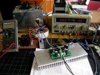
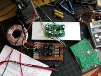
Initial test was with a bench supply on current limit, but some series resistors or bulb tester would have worked just as well. Only instrument used during inital testing was an ancient Fluke77 multi-meter. Also tested with the simplest power supply I can think of, an unregulated rectifier/filter with plenty of ripple and all kinds of other noise.
Only time any noise was apparent from the speakers was when I intentionally induced a truly gross amount of 120Hz ripple. Even then, only with one ear inches from the speaker...
I will try to post some real numbers later this week when second board is built.
Any Q., please ask.
First one of my boards built and tested this weekend, and now playing music!
(or singing, as Shaan would say)
No fireworks or smoke, offset adjusts to zero, bias settles pretty much as described in other posts above. Heat sinks stay cool, no excess heat that might indicate instability or oscillation.
Very easy to build and test (the hard work being already done by Lazy Cat and Shaan), so if anyone else is sitting on the fence, consider yourself encouraged...
Only reason it took so long to get from layout to this point is being out of town.I am testing the first board with pretty conventional components which are easily available, no long lead times, no "Un-obtainium", nothing expensive, and no audiophile components for the first pass, and the sound is very, very good.
Fairchild BC550C/560C, about $0.10/ea.
Fairchild KSA1381E/KSC3503D, ~$0.30/ea.
Renesas 2SK1058/2SJ162 ~$5.00/ea
Elecro Caps are all Panasonic FR series, between $0.45 and $1.35/ea
Input capacitor is a 10uFd Nichicon non-polar cap, $0.31
Most resistors are all generic 1%, 1/4-W
(15K resistors and feedback resistors were measured and matched)
10R resistors are 1%, 1/2W
Initial test was with a bench supply on current limit, but some series resistors or bulb tester would have worked just as well. Only instrument used during inital testing was an ancient Fluke77 multi-meter. Also tested with the simplest power supply I can think of, an unregulated rectifier/filter with plenty of ripple and all kinds of other noise.
Only time any noise was apparent from the speakers was when I intentionally induced a truly gross amount of 120Hz ripple. Even then, only with one ear inches from the speaker...
I will try to post some real numbers later this week when second board is built.
Any Q., please ask.
Attachments
-
 VSSA1Bassy1.jpg224.8 KB · Views: 797
 -
 VSSA1Bassy2.jpg263 KB · Views: 743
 -
 VSSA1Bassy3.jpg192.8 KB · Views: 242
 -
 VSSA1B_Test1.jpg229.6 KB · Views: 203
 -
 VSSA1Bpcb4.jpg324.4 KB · Views: 210
 -
 VSSA1Bpcb3.jpg343.1 KB · Views: 225
 -
 VSSA1B_Test4.jpg203.4 KB · Views: 224
 -
 VSSA1B_Test3.jpg262.5 KB · Views: 202
 -
 VSSA1B_Test2.jpg558.8 KB · Views: 212
Last edited:
Hi!
Could somebody tell me ca. how big resistor need for biasing to ca.500mW the 1.2 circuit? Instead of the 120 Ohm.
Greets:
Tyimo
Hi tyimo.
You can ask LC about this in the VSSA thread.
Hi.
Here my 3D PeeCeeCee
based on schematic post #1 & I only remove 10uF at input
Regards
Beautyful job. Now just increase the thickness of the power and output traces and etch it ASAP!
First one of my boards built and tested this weekend, and now playing music!
(or singing, as Shaan would say)
No fireworks or smoke, offset adjusts to zero, bias settles pretty much as described in other posts above. Heat sinks stay cool, no excess heat that might indicate instability or oscillation.
Very easy to build and test (the hard work being already done by Lazy Cat and Shaan), so if anyone else is sitting on the fence, consider yourself encouraged...
I am testing the first board with pretty conventional components which are easily available, no long lead times, no "Un-obtainium", nothing expensive, and no audiophile components for the first pass, and the sound is very, very good.
Fairchild BC550C/560C, about $0.10/ea.
Fairchild KSA1381E/KSC3503D, ~$0.30/ea.
Renesas 2SK1058/2SJ162 ~$5.00/ea
Elecro Caps are all Panasonic FR series, between $0.45 and $1.35/ea
Input capacitor is a 10uFd Nichicon non-polar cap, $0.31
Most resistors are all generic 1%, 1/4-W
(15K resistors and feedback resistors were measured and matched)
10R resistors are 1%, 1/2W
Initial test was with a bench supply on current limit, but some series resistors or bulb tester would have worked just as well. Only instrument used during inital testing was an ancient Fluke77 multi-meter. Also tested with the simplest power supply I can think of, an unregulated rectifier/filter with plenty of ripple and all kinds of other noise.
Only time any noise was apparent from the speakers was when I intentionally induced a truly gross amount of 120Hz ripple. Even then, only with one ear inches from the speaker...
I will try to post some real numbers later this week when second board is built.
Any Q., please ask.

It's just your own hard work paying off. Enjoy your peeceebee.
shaan
I done already, but no answers......You can ask LC about this in the VSSA thread
Hi AndrewT, thanksJohn,
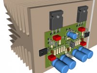
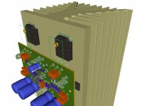
can you move the output FETs to coincide with the centre portion of the sink?
you make it better...
I change it a bit & viola
now it can be mount that wayThanks ShaanBeautyful job. Now just increase the thickness of the power and output traces and etch it ASAP!
shaan
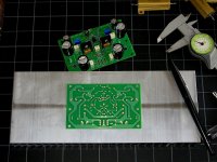
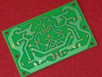
I will make it thicker later, here's update version
more easy for my "hand made PCB"
board size = 50mm * 84mm (the heatsink width is 84mm)
btw the 10uF elco parallel with 470ohm & 2x 1N4148, is this cap must be 10uF?
Because originally from LC only 1uF & non polarized one.
Please tell me the reason why change it to 10uF
Attachments
Last edited:
No.
Both transistors on the horizontal centre line arranged vertically with the lower one closer to the bottom, than the upper one to the top.
That's because the lower part of the sink runs at a lower temperature than the upper part.
You have to move the devices down below the vertical centre line to get the dissipation ability of the sink backplate and thus arrange for the temperature of the sink interface to the transistors to be at the same temperature.
BTW,
turning the assembly in post309 upside down, will cool better than the arrangement shown. The devices are far too close to the top. For a single row across a backplate the devices should be ~ 40% of the height up from the bottom, for optimum cooling performance.
Last edited:
Ok, ... maybe I'll rotate 180 degree (post # 309) or slide it downBTW,
turning the assembly in post309 upside down, will cool better than the arrangement shown. The devices are far too close to the top. For a single row across a backplate the devices should be ~ 40% of the height up from the bottom, for optimum cooling performance.
The length of heat sink is 200mm & I guess it is too long for single channel VSSA
maybe I'll put stereo on this heat sink & try your suggestion.
Thanks for your suggestion & will try latter after I finish the PeeCeeBee
An externally hosted image should be here but it was not working when we last tested it.
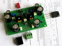
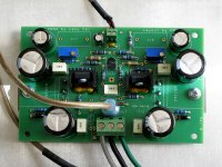
Here is a pic of the layout of the main power amplifier board, with just the Vas heat sinks and capacitors fitted. Building it on Veroboard means you can design the connections according to the size of components, rather than having to buy the components to fit the pcb! There are three power supplies per stereo amplifier, one for the input, one for the output, and one for the voltage amplifying stage (Vas). So that means three toroidal transformers per stereo amplifier, with three dual rails power supplies (one is to the right of the main board, 4 of these per stereo amplifier).. Capacitors are mostly boutique types, Nichicon, and some lovely Panasonic FM's in there, too. The white blocks are 1µF polypropylene bypass capacitors, and the big blue block is a 10µF polypropylene bias bypass cap.
I'm building two stereo amplifiers to feed a pair of floor standing Usher 604 'speakers, in a biamplification setup.
Last edited:
I done already, but no answers......
Sorry I was waiting Shaan to answer hehe
Sorry I was waiting Shaan to answer hehe
Haha don't worry you are free to help anybody without waiting for my response.
Building it on Veroboard...
BRAVO BRAVO BRAVO!
10uF elco parallel with 470ohm & 2x 1N4148, is this cap must be 10uF? Please tell me the reason why change it to 10uF
It's there to bypass the diodes for the signal, which is AC. You can use any value between 1uF and 100uF. Although it says 10uF, I'm using 100uF in my boards.
- Home
- Amplifiers
- Solid State
- PeeCeeBee