In the picture of the O-scope screen, the x and boxed x cursors are at 10% and 90% of the rise time of the waveform. The voltage and time are shown at the top of the screen... take the "Delta V2", and divide by the "Delta T", 29.6V/0.30uS... ~100V/uSec.A second look at the dT makes me think that may be I was wrong indeed. The slew rate is at least 5 times that!

@Shaan: Some of the things you cannot see from individual o-scope screen shots include close to 100% flat response from 10Hz to 50KHz, with very little phase shift. Hearing that difference requires far better speakers I am testing with, so I should probably leave that to LC and his friends...
In the picture of the O-scope screen, the x and boxed x cursors are at 10% and 90% of the rise time of the waveform. The voltage and time are shown at the top of the screen... take the "Delta V2", and divide by the "Delta T", 29.6V/0.30uS... ~100V/uSec.
That's what I did at first. OK, thanks. I was right then.
disclaimer: I don't own a scope.
Last edited:
Question, when working out 'slew' as you are, from 10% to 90% dt.
Do you use the 10% to 90% dV, or do you use full Voltage values ?...
Slew rate is defined as the maximum rate of change of a signal. That is a given definition.
It has been common engineering practice to use the middle 80% of an o-scope trace to calculate this value, but it is also true that you can use any percentage which is convenient for you own use.
The reason why we care at all, is because we want to know that the highest frequency used, will not be "slew-rate-limited" (which would become a source of distortion).
So we calculate as follows:
2*pi*Fmax*Vpk < Slew Rate
For example, at 20KHz and with 35V DC rails, required slew rate is:
2*3.141*20KHz*25V ~ 3V/uS
Lazy Cat's design, and Shaan's simplified variant of it, both have excellent performance in this regard, roughly 10 to 30 times better than required. In practice, the slew rate you calculate from a scope trace should be at least 2-3 times better (higher) than the theoretical number.
Obviously, they know that already, but the reason for checking, I wanted to know that I did not mess it up with my layout... (or, not too much, anyway
).
Last edited:
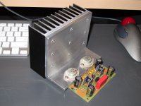
They came from an HH V800 I scrapped out that had multiple issues with the outputs not being one of them. So, I ended up with eight of each polarity guaranteed to be genuine and matched.
I wondered that!
Thanks!
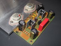
Thanks. I decided to leave both trimmers in place on the first two boards, just in case there was a change over time and temperature, but so far I have not seen it change more than a few mV.Offset is set via an additional resistor in parallel with the 15k current injectors, as per Shaan's schematic. I just used a pot to zero it out and put in the closest standard value. Offset comes in under 10mV with one standard value in place.
Next set of boards, I will try to make do with a single resistor and see how that goes, but I would like to get maybe 50-60 hours of normal volume play on the first set b/f I build another one, or change this one.
Both of my boards started w. about 15mV DC offset, but untrimmed, the measured offset changes a bit as voltage from bench supply is gradually raised. I did not really investigate that further. Trimmed to zero after warmup, seems to drift +/-5 mV. On the first board, I reset it to zero again when I switched from a regulated bench supply, to an unregulated rectifier/filter.Closely matched input pair and VAS pair will in most cases need no manual trimming and give offset of less than 20mV. Currently one of my boards has 3mV and the other has 8mV, untouched.
How do you match your resistors, by hand or using a meter/transistor tester?
How do you match your resistors, by hand or using a meter/transistor tester?
By hand with a meter.
Only the feedback network is matched.
Last edited:
- Home
- Amplifiers
- Solid State
- PeeCeeBee