I used 500K, because it was more easily available when I ordered the parts, but I would use 1M if available. Trim pots were adjusted to 50% before installation.Was it 1M trimpot or less?
The board is laid out so that turning the screw in one direction on both sides has the same effect on the offset voltage. In other words, the wiper-common on the positive rail is opposite the wiper-common on the negative rail.
If the intent is to just set the offset once and leave it, Shaan's method is best (and costs less). I was not that confident, and wanted to see how the offset changes with temperature, and after a few hours of operation (answer is, very little).
TO-3 PeeCeeBee
I've received some interest via PM for printable art for my TO-3 based layout, so here is PDF files for printing / making film. There's one for Japanese ECB pinouts and one for BC5xxC CBE pinouts, so be mindful of which you choose to use. Component layout is found at post #218 here
Hope everyone who uses this enjoys it as much as I am.
Attachments
Last edited:
Yes, I will do that later today. What kind of file do you want posted here, something like you posted at the beginning of this thread? Silkscreen and bottom copper? (I only ask because I cannot edit posts to change it later)Hi PMI, would you please upload your artwork in pdf too?
Tested PeeCeeBee Designs
Shaan,
I agree that for those who have sucessfully done a PeeCeeBee of their own design that they should ideally be linked to in the first post so folks can easly find them. Though they are all based on the same design one layout may suit some users better than others. Excellent sugestion. How many proven layouts so far? Obviously Shaan, PMI, Naf, Boyet and myself immediately come to mind.
Jason
Nice nice nice!Thanks for sharing Jason.
Hi PMI, would you please upload your artwork in pdf too?
How about putting links to tested peeceebee designs in the first post?
Shaan,
I agree that for those who have sucessfully done a PeeCeeBee of their own design that they should ideally be linked to in the first post so folks can easly find them. Though they are all based on the same design one layout may suit some users better than others. Excellent sugestion. How many proven layouts so far? Obviously Shaan, PMI, Naf, Boyet and myself immediately come to mind.
Jason
What kind of file do you want posted...
PDF. 1)Bottom layout, 2)Silk screen, 3)Solder mask.
Plus another PDF with the layout and silkscreen superimposed, if possible.
I agree that for those who have sucessfully done a PeeCeeBee of their own design that they should ideally be linked to in the first post so folks can easly find them. Though they are all based on the same design one layout may suit some users better than others.
Exactly!
How many proven layouts so far? Obviously Shaan, PMI, Naf, Boyet and myself immediately come to mind.
Yes. Naf and Boyet are requested to kindly upload their own designs too. Thanks in advance.
")
To all, please quote board dimensions when posting your PeeCeeBee designs. Thank you.
........................................................
........................................................
My treasure...
GRRRRRR!
I bet If I lived near your house I would... ...
OKAY OKAY, I'm ultra jelly!
shaan
p.s.: John Bali and Borys too seem to have designs of their own. Please test your boards asap and tell the story! Waiting...
Last edited:
GRRRRRR!
I bet If I lived near your house I would... ...
OKAY OKAY, I'm ultra jelly!
shaan
You wish, my cat keeps an eye on Fets.


Regards zeoN_Rider
My treasure:
OEM Hitachi 2SK135 and 2SJ50
regards zeoN_Rider
Exactly what I had to work with, only I have twice as many
.First, I would like to thank Lazy Cat and Shaan for an outstanding design, and for proving me and everyone else who will be using it with such excellent examples to follow.
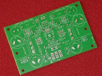
PDF Files attached, as requested, including silk screen, bottom copper, silkscreen and bottom copper overlapped, with heatsink location shown in green. The files are 1:1 scale (100%). Dimensions are 102x64mm (approximately 4x2.5, 10 inches square). My BOM is also attached.
Please note that I have NOT etched any boards myself (mine came from a prototype board company), so if you intend to etch your own boards, please examine the files carefully. So, the boards you see in my pics are only assembled by me, not printed or etched by me. Therefore they have plated holes, gold pads top and bottom, solder mask top and bottom.
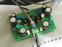
Two boards are assembled and tested, one has been working for about a week, and two are running as a pair for the last 3-4 days. I have sent out a couple sets of boards to other DiyAudio members, and I have a couple extra spare sets for anyone else who may be interested.
Offset adjust, bias, etc. are as described by Shaan. Bias on my boards is set by the two diodes, I have not installed the parallel resistor, although I may do so in the future.
PDF Files attached, as requested, including silk screen, bottom copper, silkscreen and bottom copper overlapped, with heatsink location shown in green. The files are 1:1 scale (100%). Dimensions are 102x64mm (approximately 4x2.5, 10 inches square). My BOM is also attached.
Please note that I have NOT etched any boards myself (mine came from a prototype board company), so if you intend to etch your own boards, please examine the files carefully. So, the boards you see in my pics are only assembled by me, not printed or etched by me. Therefore they have plated holes, gold pads top and bottom, solder mask top and bottom.
Two boards are assembled and tested, one has been working for about a week, and two are running as a pair for the last 3-4 days. I have sent out a couple sets of boards to other DiyAudio members, and I have a couple extra spare sets for anyone else who may be interested.
Offset adjust, bias, etc. are as described by Shaan. Bias on my boards is set by the two diodes, I have not installed the parallel resistor, although I may do so in the future.
Attachments
Last edited:
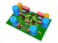
The following series of pics shows a 3D rendering of the board layout, followed by a bare board, and assembled board. Note that the first image shows the common Faston-type flat tab connector for the power and speaker out connections.
The other pics of the boards show a 3-pos terminal block (which can be installed in the same place) which I am using only for test purposes.
The driver transistors are TO-126 mounted on 10x15x20 mm heatsink. The main heatsink is 10x4x1.3", 0.65C/W (from HeatsinkUSA, one of the companies which sells products here on DiyAudio).
There are no unique, expensive, or otherwise unobtainable parts. The the best of my knowledge, every component used has at least one second source.
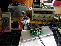
Both boards I have assembled so far have been tested first with a variable bench supply, then with a variac, and 250 VA transformer/rectifier/filter, +/-35V DC nominal, 36-37V actual rail voltage, which is what I have been using up to now when I listen to the amp in stereo.
Once installed in the case, I will probably use an adjustable linear power supply.
Any questions, please ask or send a pm.
The other pics of the boards show a 3-pos terminal block (which can be installed in the same place) which I am using only for test purposes.
The driver transistors are TO-126 mounted on 10x15x20 mm heatsink. The main heatsink is 10x4x1.3", 0.65C/W (from HeatsinkUSA, one of the companies which sells products here on DiyAudio).
There are no unique, expensive, or otherwise unobtainable parts. The the best of my knowledge, every component used has at least one second source.
Both boards I have assembled so far have been tested first with a variable bench supply, then with a variac, and 250 VA transformer/rectifier/filter, +/-35V DC nominal, 36-37V actual rail voltage, which is what I have been using up to now when I listen to the amp in stereo.
Once installed in the case, I will probably use an adjustable linear power supply.
Any questions, please ask or send a pm.
Attachments
My amp has ''beded in'' for good few days playing, I must say it only gets better.
Mid and high are acurate, detailed and very pleased to listen to. Bass i do not know exacly couse I have only small 15cm speakers with seas 22faf/g(but impression is good).
Thanks very very much to LazyCat Shaan and others hard working people.
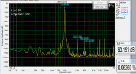
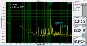
Today I made quick meas, just for fun.
Mid and high are acurate, detailed and very pleased to listen to. Bass i do not know exacly couse I have only small 15cm speakers with seas 22faf/g(but impression is good).
Thanks very very much to LazyCat Shaan and others hard working people.
Today I made quick meas, just for fun.
Attachments
Are the 7th and 9th real, or artifacts of your measurement procedure?
I will check that tomorrow. I am using audiotrak prodigy cube for meas, in output is opa2134 and dac is Tenor TE7022L as far i remember.
- Home
- Amplifiers
- Solid State
- PeeCeeBee