... real output stages have finite bandwidth and contribute excess phase. This in turn influences the maximum achievable unity loop gain frequency for a given stability criteria. That in turn directly affects available loop gain in the audio band....
Hi Bob
I completely concur about the importance of non idealities but I think Mike's point is that since equivalent TMC and TPC will have essentially identical loop gain about the OPS then the non ideality of the OPS does not affect a comparison between TMC and TPC.
At least, I hope that was Mike's point.
The converse is that the different loop gain about the IPS mean that non ideality there does affect the comparison between TPC and TMC.
Best wishes
David
Cherry's FB network
Hi David,
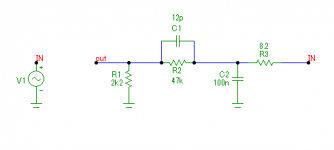
It's just the opposite. It provides some lag compensation. See pic.
Hi Wahab,
With a constant frequency FB ratio, the phase will also be constant (except in case of an all-pass filter, of course. But this is not an all-pass filter).
What we see is some lag compensation, due to paralleling of R1 with C1 and C2 in series.
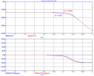
BTW, the value of C1 is a bit too small. Actually, it should be 17.4pF for equal time constants (see red curve)
Anyhow, I don't understand the rationales behind this FB network. Besides, it might introduce a little bit extra distortion, as distortion free caps of 100nF are hard to get and expensive.
Cheers,
E.
It is connected to Zobel cap but I think that Cherry's quote implies it still provides some lead. .................
Best wishes
David
Hi David,
It's just the opposite. It provides some lag compensation. See pic.
Hi Edmond ,
.................
The 12pF cap will in principle act as a high pass network whose effect
should be reciprocal of the zobel network and hence provide a frequency
constant feedback ratio but it will also provide inherently a phase lead
compensation.
Hi Wahab,
With a constant frequency FB ratio, the phase will also be constant (except in case of an all-pass filter, of course. But this is not an all-pass filter).
What we see is some lag compensation, due to paralleling of R1 with C1 and C2 in series.
BTW, the value of C1 is a bit too small. Actually, it should be 17.4pF for equal time constants (see red curve)
Anyhow, I don't understand the rationales behind this FB network. Besides, it might introduce a little bit extra distortion, as distortion free caps of 100nF are hard to get and expensive.
Cheers,
E.
Attachments
Last edited:
Hi Wahab,
With a constant frequency FB ratio, the phase will also be constant (except in case of an all-pass filter, of course. But this is not an all-pass filter).
What we see is some lag compensation, due to paralleling of R1 with C1 and C2 in series.
BTW, the value of C1 is a bit too small. Actually, it should be 17.4pF for equal time constants (see red curve)
Anyhow, I don't understand the rationales behind this FB network. Besides, it might introduce a little bit extra distortion, as distortion free caps of 100nF are hard to get and expensive.
Cheers,
E.
Agree that the rational of such a design Escapes me as well
but Cherry must have his reasons...
As you pointed it the cap value is sub optimal and i also
find a nearby value , 18-22pF, as being more adequate ,
simulation done with a whole amplifier schematic.
Feedback lead capacitor and EMI
If you are concerned about EMI ingress at the output of the amplifier from the speaker cable on sound quality, then the use of a lead capacitor across the feedback resistor should be a concern.
The speaker cable can be a very good antenna.
Whatever EMI reaches the output stage will be about 20X larger back at the input stage when the lead capacitor is used in the feedback network. Without the lead capacitor, such EMI at the output stage is reduced by a factor of about 20 for an amplifier with a gain of 20. I discuss EMI ingress in Chapter 18.2, “EMI Ingress: Antennas Everywhere”. The subject of EMI's effect on sound quality is a somewhat muddy one, but if you believe it is a concern, then using the lead capacitor can make it worse.
The lead capacitor provides a direct path for EMI from the speaker cable to enter the sensitive input stage. For this reason, I prefer to achieve good feedback loop stability without resort to a lead capacitor across the feedback resistor.
Cheers,
Bob
Agree that the rational of such a design Escapes me as well but Cherry must have his reasons...
.......
Every genius has his peculiarities. Perhaps that's the reason.
")
It's in reducing speaker cable interference that the Full Thiele Network shows it's advantage over the Zobel used alone.
When the Thiele Network is expanded into the Pi version, that advantage becomes even greater.
Now to the question.
Is there any advantage to splitting the Pi version to become a balanced filter on the two lines feeding the speaker cables?
Zobel = R+C to Ground
Thiele = R+C to Ground plus R//L to speaker terminal.
Pi Thiele = R+c to Ground plus r//L to speaker terminal plus r+c across speaker terminals.
note the "smaller" r & c values in the Pi version. where R=2r and C~=2c
Folks,
In going through all of this feedback compensation discussion, I was reminded of what I called "Bridged T" compensation on pages 178-179 of my book. This is where a small bridging capacitor is added across the T of TPC. It tames the very large loop gain peak that can occur in the audio band (often in the vicinity of 1kHz - see Figure 9.5) when TPC is used.
Hi Bob, in your second edition you should note that this configuration is extremely sensitive to the value of the bridging capacitor. Just a few extra pF can split the two poles very far apart in frequency and result in diminished loop gain.
An alternative method of damping/splitting the poles is to add a capacitor in series with the network's resistor, as demonstrated in my two-pole-compensation AES convention paper (be sure to read the addendum!). This approach is less sensitive to component value and allows finer control over the position of the two poles. I suggested a possible name for this compensation as "split two-pole compensation" as the two poles can be split apart in frequency (standard two-pole comp. results in complex (coincident frequency) poles; the Q of which depends upon minor loop topology, i.e. cascoding in input stage, single transistor/beta-enhanced/cascoded/beta-enhanced+cascoded TIS/VAS).
I've not tried Godfrey's suggested alternative but things he has written suggest that this technique is also less sensitive to component value.
Given how sensitive two-pole compensation is to the value of capacitance across the bridge, I think it makes sense to shield this node from parasitic capacitances and use a less sensitive technique to damp/split the poles.
Last edited:
It's in reducing speaker cable interference that the Full Thiele Network shows it's advantage over the Zobel used alone.
When the Thiele Network is expanded into the Pi version, that advantage becomes even greater.
Now to the question.
Is there any advantage to splitting the Pi version to become a balanced filter on the two lines feeding the speaker cables?
Zobel = R+C to Ground
Thiele = R+C to Ground plus R//L to speaker terminal.
Pi Thiele = R+c to Ground plus r//L to speaker terminal plus r+c across speaker terminals.
note the "smaller" r & c values in the Pi version. where R=2r and C~=2c
However, all those required damping resistors inhibit high-frequency attenuation. I'm not convinced that these networks are as good at rejecting high-frequency EMI as Mike asserts. Perhaps he could be more precise about topology and component values he thinks should be used in the network that interfaces the amplifier output to the speaker terminals?
Trouble is the bridge cap is only a few pF to start with. Add a few more and you've doubled it. This also makes me think about stray capacitance e.g. between PCB tracks. With careful layout I wouldn't be surprised if one could "bridge the T" with stray capacitance. Similarly, it's probably possible to screw up the compensation with poor layout.note that this configuration is extremely sensitive to the value of the bridging capacitor. Just a few extra pF can....
I've not tried Godfrey's suggested alternative but things he has written suggest that this technique is also less sensitive to component value.
I don't think it's less sensitive, but I was doing something else as well that helps, although it's probably anathema to the "more feedback at any cost" brigade.
The trick is to deliberately limit the open loop gain. That way you know what the open loop gain is in the audio band, and what frequency the peak is at. Without that information, you're shooting in the dark trying to optimally damp the peak.
Trouble is the bridge cap is only a few pF to start with. Add a few more and you've doubled it. This also makes me think about stray capacitance e.g. between PCB tracks. With careful layout I wouldn't be surprised if one could "bridge the T" with stray capacitance. Similarly, it's probably possible to screw up the compensation with poor layout.
Yes, this is what I mean by sensitivity. In percentage terms, it's not sensitive, it's just that when you look at it in terms of the absolute changes in capacitance, it's just a few pF and that's not too hard to introduce parasitically in your layout.
The trick is to deliberately limit the open loop gain. That way you know what the open loop gain is in the audio band, and what frequency the peak is at. Without that information, you're shooting in the dark trying to optimally damp the peak.
Yes, aiming at critical damping of the poles is a non-starter in real-world amplifiers, especially if you want to build a lot of them (i.e. commercial venture). But if you simply wish to split the poles into two real ones, it's possible to pick component values that guarantee that that will happen across all reasonable component variations/manufacturing tolerances.
Deliberately limiting open loop gain will also work and is interesting to experiment with.
Last edited:
I think the speaker line filter needs to be designed with the amplifier's characteristics in mind. For instance, some amps are more resistant to EMI; they have a significant output impedance at RF and the LTP doesn't respond much to RF entering the output. Other amps have low output impedance at RF and the LTP is very responsive to RF entering the output. I think these two cases should be treated differently. There are multiple types of output impedance curves and this matters for stability and step response.
I think the EMI issue needs to be seen in proportion. What is the ultimate issue with EMI? As I understand it causes the fast gain stages to saturate, and if not, it agitates the operating points and causes problems that way.
For a circuit highly susceptible to EMI, no filter may be enough. So do such circuits occur in practice? I guess it depends on who you ask, especially when it comes to DIYAudio.
Different amps react differently to EMI, depending especially depending on the compensation method. Multi-pole compensations tend to make RF susceptibility worse because the input stage must be loaded more in order to bring the phase back to normal.
If one determines the saturation point of each stage, one can use this information is SPICE to make a plot for different EMI conditions that shows at which frequencies each stage will saturate. One can see which stage will saturate first. Because BJT distortion is proportional to Iq, most amps already tend to have these saturation points close to each other because this is also the point where distortion is distributed between the stages and so total distortion is minimum.
Different ways of implementing TPC can make a significant difference in the EMI response of the individual stages.
TPC generally works by relieving the load at one frequency and increasing the load at another to compensate. At the extreme, you can get an amplifier that reports a BW of 10MHz in AC analysis but in practice, it won't go past 1MHz without slew rate limiting with any significant signal. Such an amplifier will be highly susceptible to EMI.
Ultimately, it is not in our best interest to rob Peter to pay Paul, in this case. If we can avoid increasing loading, then we get lower distortion AND higher EMI tolerance.
Edmund seems to have made strides in this category, by using external compensation as much as possible. By external, I mean compensation that does not work by loading stages, but rather by manipulating the input to those stages. After all, when you produce stability by loading a stage, you are in fact using that stage as an impedance converter, and creating a virtual impedance at it's input. Why do this if a passive component will suffice?
Because passive components don't saturate and don't cause slew limits, an amp designed this way could be extremely tolerant to EMI.
I suspect that an amplifier that needs a lot of RF filtering is an amp that could be improved substantially with special attention to the compensation scheme. Unfortunately many amps with advanced compensation techniques may fall into this category.
What do you think?
Hi Bob
Let's not forget that the same effect can be achieved with an extra resistor instead of an extra capacitor, as I explained here. As a practical example, the compensation network I showed in this post uses that technique.
I feel that's a worthwhile modification. Perhaps you'd care to play with the idea to confirm it works, and maybe mention it as an alternative in the next addition?
Regards Godfrey
p.s. Sorry, don't know who to credit for the original idea.
Hi Godfrey,
I looked back in my simulations quite awhile back, when I was experimenting with the bridging capacitor for my book, and saw that I had actually done some with a resistor across C2. I simulated it and confirmed that is does what is desired, but for some reason never took it further. So, bottom line, your point about the resistor working is right. I did not try the experiment with the resistor across C1.
Your point about 3pF being rather small is a good one. I had set it to 3pF as being 1/10 the 30pF value of capacitance that would be used with ordinary Miller compensation, so as to limit the "lift" to about 20dB or less.
The resistor approach seems potentially more attractive, with its value wanting to be about 10X the value of the TPC shunt resistor to limit the "lift" to 20dB or less. That would put the resistor in the range of 200k for the 60pF - 20k - 60pF TPC network I showed in my book.
The caveat, given the values I used, is that even in the resistor approach your concern about getting a couple of pF of stray across the bridge is still a valid one. I've found that it is pretty hard to get 3pF of stray between two nodes in a decent layout. Also, a design where the nominal values of capacitors is set higher, with a corresponding higher input stage transconductance for the same ULGF, will be correspondingly less sensitive to a given amount of bridging stray.
Finally, TPC (or TMC) schemes that use non-equal values for C1 and C2 may exhibit more or less sensitivity to stray bridging capacitance.
Cheers,
Bob
Here a real world example of Bob's "Bridged TPC" merged with Douglas's "Blameless":
http://www.diyaudio.com/forums/soli...ormance-class-ab-power-amp-200w8r-400w4r.html
Many thx to Bob Cordell and Douglas Self for their excellent books.
Best regards,
Toni
http://www.diyaudio.com/forums/soli...ormance-class-ab-power-amp-200w8r-400w4r.html
Many thx to Bob Cordell and Douglas Self for their excellent books.
Best regards,
Toni
I think the question is what kind of peak it is. I see an analogy with band filters. A parallel LC resonator shunting a signal will draw zero current at the peak, presenting no danger to preceding stages. If instead we shunt the signal with a series LC resonator, it will act as a short at the peak and may cause a lot of damage.
So, does the loop gain peak act as a benign resonator or a destructive one? If destructive, there will be a stage that is ringing and this should show up in transient analysis.
So, does the loop gain peak act as a benign resonator or a destructive one? If destructive, there will be a stage that is ringing and this should show up in transient analysis.
Hi Godfrey,
I looked back in my simulations quite awhile back, when I was experimenting with the bridging capacitor for my book, and saw that I had actually done some with a resistor across C2. I simulated it and confirmed that is does what is desired, but for some reason never took it further. So, bottom line, your point about the resistor working is right. I did not try the experiment with the resistor across C1.
Your point about 3pF being rather small is a good one. I had set it to 3pF as being 1/10 the 30pF value of capacitance that would be used with ordinary Miller compensation, so as to limit the "lift" to about 20dB or less.
The resistor approach seems potentially more attractive, with its value wanting to be about 10X the value of the TPC shunt resistor to limit the "lift" to 20dB or less. That would put the resistor in the range of 200k for the 60pF - 20k - 60pF TPC network I showed in my book.
The caveat, given the values I used, is that even in the resistor approach your concern about getting a couple of pF of stray across the bridge is still a valid one. I've found that it is pretty hard to get 3pF of stray between two nodes in a decent layout. Also, a design where the nominal values of capacitors is set higher, with a corresponding higher input stage transconductance for the same ULGF, will be correspondingly less sensitive to a given amount of bridging stray.
Finally, TPC (or TMC) schemes that use non-equal values for C1 and C2 may exhibit more or less sensitivity to stray bridging capacitance.
Cheers,
Bob
Hi Bob,
Here is practical example of bridged TMC with a resistor parallel to the bridge capacitance, and I am listening it for a year with great satisfation. http://www.diyaudio.com/forums/solid-state/182554-thermaltrak-tmc-amp-7.html#post2964648 look pdf file. My simulation showed higher value resistor then your, in the range 2Meg to 10Meg.
BR Damir
Hi Mike, It is important for you to understand that real output stages have finite bandwidth and contribute excess phase.
I do understand. The point I was making, which you probably haven't understood, is that if you design a stable TPC network and simply connect the resistor to the output, you'll then have a "TMC" network which gives the same loop gain in the audio band about the second stage and the output stage as the TPC network gives about the major loop, regardless of whether you're using an ideal output stage or a one consisting of real transistors.
Cannot be Michael. You have a big fat pole in the o/p stage that I am afraid will just not go away - and especially if you are using bipolars. That's one of the main reasons all this MC, MIC, TPC, TMC etc stuff. Otherwise, you could probably stick a pole at 50 or 100 kHz and be done with it and get sub 1 ppm without even trying.
Hi Bonsai,
I am painfully aware of the limitations imposed by output stage singularities.
The point I was making, however, is that if you design a stable TPC network and simply connect the resistor to the output, you'll then have a "TMC" network which gives the same loop gain in the audio band about the second stage and the output stage as the TPC network gives about the major loop, regardless of whether you're using an ideal output stage or a one consisting of real transistors.
Hi Bob, in your second edition you should note that this configuration is extremely sensitive to the value of the bridging capacitor. Just a few extra pF can split the two poles very far apart in frequency and result in diminished loop gain.
This is true. The only thing missing is an explanation in respect of why you and Bob consider it necessary to split the coincident poles.
In my view the resonant peak is completely innocuous: there is no need to reduce loop transmission by splitting the coincident poles.
Last edited:
TPC midrange loop gain peaks, TMC minor loop ...
Has ANYONE seen ANY evidence, whether SIM or 'real life', that this midrange peak in TPC loop gain has an effect on the Final (closed loop) response? Ringing, response peaks, overload behaviour ... anything?
I was really concerned about this circa 1990 but couldn't find anything.
_______________
TMC minor loop gain
Michael, not that I'm worthy to join the erudite discussion on equivalence of TPC / TMC ... but could you tell me where you would put a Tian probe on [B]http://www.diyaudio.com/forums/solid-state/235188-tpc-vs-tmc-vs-pure-cherry.html[/B] to measure your 'total loop gain in the minor loop' for TMC?
Absolutely.In my view the resonant peak is completely innocuous: there is no need to reduce loop transmission by splitting the coincident poles.
Has ANYONE seen ANY evidence, whether SIM or 'real life', that this midrange peak in TPC loop gain has an effect on the Final (closed loop) response? Ringing, response peaks, overload behaviour ... anything?
I was really concerned about this circa 1990 but couldn't find anything.
_______________
TMC minor loop gain
Michael, not that I'm worthy to join the erudite discussion on equivalence of TPC / TMC ... but could you tell me where you would put a Tian probe on [B]http://www.diyaudio.com/forums/solid-state/235188-tpc-vs-tmc-vs-pure-cherry.html[/B] to measure your 'total loop gain in the minor loop' for TMC?
Last edited:
......but could you tell me where you would put a Tian probe .....to measure your 'total loop gain in the minor loop' for TMC?
I will post a circuit sim later.
- Home
- Amplifiers
- Solid State
- Bob Cordell's Power amplifier book