Some considerations about the clock system in BDP105.
It is noticeable a quite big improvement in this system since 95 model. The old model had clocks everywhere for the all stages. Two clocks for the main processor, two clocks for the two DACs, and so on. And some of those were actually resonators...
Oppo`s designers has decided to do something with this clock system, and the result it is good in this last model. They had a thought to integrate/unify the clock system even more, but for some reasons the 105 model it were out like it is.
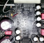
The clock system is quite sophisticated in this 105 model. It were redesigned completely the clock for the DACs. This clock is generated now from an 54Mhz oscillator, powered from a own very low noise regulator, and the grounding is quite carefully designed around this oscillator. The resulting clock signal is further converted to be transported away (differentially) to the other (multichannels) DAC.
I noticed that it were designed on the main analogue PCB a place for an micro BNC connector. This connector it were not planted in this model. This make me think that the designers will do more in the new model about this clock system...
So I decided to do it this "more" right now for this 105 model...
What about use this 54Hz oscillator to generate the 27Mhz clock for the main processor?
I`m quite sure that Oppo designers work on the same for the next model. It seems to me that the master clock it will be planted in this place it is designed now, and different clock frequencies it will be distributed further to the right devices.
So, as thought, as done. I divided the DACs 54Mhz clock frequency to 27Mhz and send it to the main processor. It just works fine!
Now it may be improved this idea to get the most out of it. I now regret the ordering of a quite big lot of 54Mhz SAW oscillators... I should want 108Mhz oscillator as master clock for DACs and divided by 4 to get 27Mhz for the processor. For sure an higher frequency oscillator behave better, when about stability and jitter/phase noise figures. And not least, the DACs work much better at this (around) 100Mhz frequency.
We were a little bit too fast with the order for those SAW 54Mhz oscillators. isn't it Joe?
But anyway, I think is a better way to go with an unified clock system, synchronized, with the same quality, same jitter and so on. I`m sure Oppo think about the same...
Well, but how it sounds all this? I need more time to listen... I can only remark for now a little bit more precise/accurate sound... So, the quick conclusion is that is not a dramatic improvement in sound/picture quality. I mean more than I had before when an I used an dedicated 27Mhz oscillator instead for the original resonator, for the processor... But I have used now only the original oscillator Oppo has planted on the PCB, so I do not trust very much the high quality of that. Anyway, some more work is to be done in this direction...
It is noticeable a quite big improvement in this system since 95 model. The old model had clocks everywhere for the all stages. Two clocks for the main processor, two clocks for the two DACs, and so on. And some of those were actually resonators...
Oppo`s designers has decided to do something with this clock system, and the result it is good in this last model. They had a thought to integrate/unify the clock system even more, but for some reasons the 105 model it were out like it is.
The clock system is quite sophisticated in this 105 model. It were redesigned completely the clock for the DACs. This clock is generated now from an 54Mhz oscillator, powered from a own very low noise regulator, and the grounding is quite carefully designed around this oscillator. The resulting clock signal is further converted to be transported away (differentially) to the other (multichannels) DAC.
I noticed that it were designed on the main analogue PCB a place for an micro BNC connector. This connector it were not planted in this model. This make me think that the designers will do more in the new model about this clock system...
So I decided to do it this "more" right now for this 105 model...
What about use this 54Hz oscillator to generate the 27Mhz clock for the main processor?
I`m quite sure that Oppo designers work on the same for the next model. It seems to me that the master clock it will be planted in this place it is designed now, and different clock frequencies it will be distributed further to the right devices.
So, as thought, as done. I divided the DACs 54Mhz clock frequency to 27Mhz and send it to the main processor. It just works fine!
Now it may be improved this idea to get the most out of it. I now regret the ordering of a quite big lot of 54Mhz SAW oscillators... I should want 108Mhz oscillator as master clock for DACs and divided by 4 to get 27Mhz for the processor. For sure an higher frequency oscillator behave better, when about stability and jitter/phase noise figures. And not least, the DACs work much better at this (around) 100Mhz frequency.
We were a little bit too fast with the order for those SAW 54Mhz oscillators. isn't it Joe?
But anyway, I think is a better way to go with an unified clock system, synchronized, with the same quality, same jitter and so on. I`m sure Oppo think about the same...
Well, but how it sounds all this? I need more time to listen... I can only remark for now a little bit more precise/accurate sound... So, the quick conclusion is that is not a dramatic improvement in sound/picture quality. I mean more than I had before when an I used an dedicated 27Mhz oscillator instead for the original resonator, for the processor... But I have used now only the original oscillator Oppo has planted on the PCB, so I do not trust very much the high quality of that. Anyway, some more work is to be done in this direction...
Attachments
Last edited:
After listening more, I may to say that definitely the sound have much more fidelity, or is more accurate and detailed, using this synchronized clocking for DACs and processor. The bass is extremely deep and very detailed too. I could hear details I was never aware before in some music pieces I use to listen (or used as test).
I have also say that the setup I used and described above (a divider device with quite big propagation delay, original oscillator with doubtful quality level) is only for experimentation purposes, and that because the sound improvement may be not very obviously. My actual goal in this instance were/is to see if works...
For sure using much better divider device, better quality and maybe higher frequency oscillator, and at last improved transmission line, this way to clock the player it may bring very good results.
Keep working on it...
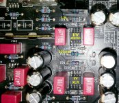
I found something quite strange here. They used different values resistors for I/V - stereo. As I knew it may be the same/identical value I/V resistors for those differential DAC +/- outputs...
On XLR stage there is as it should, identical value resistors on I/V.
Any clue about what it could be the reason for such design?
On XLR stage there is as it should, identical value resistors on I/V.
Any clue about what it could be the reason for such design?
Attachments
I think I were not very precise in earlier post about the offset I found on output (RCA) of my device. So I correct it here: +3,2mV on one channel and -4,8 on another one. This measurement I have made with that strange setup with unequal I/V resistors in place on (only) RCA channels.
I have replaced I/V resistors with equal values, and the offset on output it became +3,8mV and +4,1mV. I think this is a more normal functioning of the stage. This offset is possible to be set further down to 0 by modifying appropriate circuit. There is an main offset control circuit for all of the I/V circuits for all the channels of ESS9018. So, small differences it may appear on some channels as not all opamps are identical...
I still wonder about this strange way to treat the differential output of the DAC channels on RCA outputs. It may be happen that only my player had a production fault?
I appreciate a confirmation or not about this fact from another one.
Last edited:
I see, this is quite easy to understand. But:
In this case there is about a designed unbalanced circuit. Is not about something which is only happen in production, or by chance... On RCA channels there are planted different values I/V resistors on differential output of the DAC. This may be only wrong design. If one can see any advantages of such design, please clarify.
The unbalance is possible to be fixed in DC coupling. There is no need for caps to prevent this. An 4mV offset is not very bad and it may be accepted by the most of amplifiers.
A right adjusted offset (offset control circuit) it may bring the outputs even more very near zero.
The unbalance is present only in RCA line, but not in XLR outputs...
I have planted equal value resistors on I/V stage (RCA), and I have balanced the both differential channels of the DAC. Much better result, and more normal/lower offset on outputs in DC coupling. This way it should function. Why introduce unbalance by design and then put caps on outputs to isolate the high DC offset? Sorry, but is a nonsense here...
Maybe is about a patent in this: how the differential circuits can perform better when it function in unbalanced mode...
I have now 0,6/0,9mV offset on channels (DC coupled). 3,8V on AVCC of ESS9018, equal +/- tensions on both finals and I/V opamps, and (only...) 54Mhz clock (battery powered) divided to 27Mhz for processor. Not the original oscillator, but not a very special one either ... It seems that everything else oscillator is better than the original one...
The depth in sound scene is obviously, the deep bass and percussions vibrations have good punch and it feels well in the whole body, not only hearable. Exceptional definition and precision on high. Good 3D separation with speakers full transparent in the sound stage
And is not finished yet with all the necessary/possible mods... I just wonder how it may be when all will be finish...
I'm quite satisfied so far...
Last edited:
The unbalance is why they had to add the output caps.
Hi John, Hi Coris
I noticed the asymmetrical I/V as well. Only used on the unbalanced (it wouldn't work balanced for obvious reasons) and then gets summed after I/V stage. Hadn't thought that would get DC offset, but yes, that could be the reason for output caps.
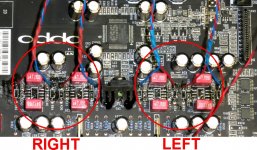
As it is, I eschew the post-DAC altogether and parallel up the DAC's two outputs. For those who may want to do the same and use their own post-DAC, this pic shows the correct phase to parallel (or they cancel out if you get it wrong.
See below pic. Red to Red and Blue to Blue.
I hear that Burson and others no longer parallel the DAC's outputs and they claim that it sounds better single. This is what I have heard said (not heard it myself) and it is also clear that Oppo has followed the same line. But I have a theory about that, they are using opamps, lots of feedback I/V and even Burson, even though their's is a discrete opamp, it is still an opamp. It may well be that with opamps, single works better - that DAC output Z = 780 Ohm means easier conditions for the opamp, less "hot" and also less potential slew type distortion that can degrade sound.
I don't use opamps here. I dump the outputs (note plural) straight into 3R3 resistors (pulls the 1.65V DC offset to ground, creates an offset current of 2.1mA per phase), then use a zero feedback, very fast, low noise (a la phono stage sans EQ) voltage amp to bring it up to 2.2V approx. With the Oppo 105 I need to double the gain. All DC coupled and the DC Offset is nulled.
Sounds great.
Cheers, Joe
Attachments
Last edited:
I should want 108Mhz oscillator as master clock for DACs and divided by 4 to get 27Mhz for the processor. For sure an higher frequency oscillator behave better, when about stability and jitter/phase noise figures. And not least, the DACs work much better at this (around) 100Mhz frequency.
Can you find a chip that can take a 108MHz input - the divide by four is not a problem, it is the input frequency. The NXP 74HC4040N is rated at 98MHz.
Hi Joe
Thanks for your input.There are dividers which it works in Ghz domain. I can not prove this statement yet by fakts. I just ordered and I`m waiting for test it... I'd love to go that way if possible, but I can say that I'm very impressed by the performances when clocking with 54Mhz.
When about AC coupling reasons, I may say that I'm not (yet) satisfied with your possible explanation. If it were to have DC offset on unbalanced outputs (RCA), then it were reasonable to use AC coupling only on those outputs. This player is entirely AC coupled, even on balanced stage. So...
As one can notice, the unbalanced I/Vs on the RCA channels are symmetric designed (unbalanced I/V resistors), and have nothing to do with the phases (you show in your pic) coming from the DAC. We talk here about unbalanced output, but I think that the phases coming from the DAC differential outputs it may be symmetric and equal treated by the I/V converter. I still do not get the advantages of 50% unbalanced I/V conversion, which is reflected further in the summing/final opamp. There is a phase from DAC differential output which is 50% bigger level than another one after this I/V stage...
So, we may still finding the right explanation... It should be easier to have an answer from an Oppo designer here
There are dividers which it works in Ghz domain. I can not prove this statement yet by fakts. I just ordered and I`m waiting for test it... I'd love to go that way if possible, but I can say that I'm very impressed by the performances when clocking with 54Mhz.
Would love to know what those dividers are. The NXP 74HC4040N from Farnell (380-880) could be used with 54MHz SAW and give both that plus 27MHz using that chip. They are limited to 98MHz input. Maybe 108MHz is not a stretch, being 10% increase is within tolerance? I have tried to find an alternative, so if you have found one, I am interested to know.
I am not sure that using identical clock source for both is an advantage? Not saying there isn't, but sure open to any explanation why so.
Cheers, Joe
I'd not recommend the HC4040 for clock division - reason being its a ripple counter. This means each stage's clock is derived from the previous stage - jitter gets added by each stage. A better choice would be something like 74LVC161 because its synchronous - all outputs are derived directly from the input clock.
I'd not recommend the HC4040 for clock division - reason being its a ripple counter. This means each stage's clock is derived from the previous stage - jitter gets added by each stage. A better choice would be something like 74LVC161 because its synchronous - all outputs are derived directly from the input clock.
Only using the HC4040 as single stage, from 50MHz to 25MHz (Oppo 95) and 54MHz to 27MHz (Oppo 105). The 74LVC161 form factor is 48 pin SMD and the non-SMD HC4040 so easy to use.
The "SAW" advantage is easily coming through the HC4040, and are both powered by the Terra Firma 3.3V - and it adds only a modest amount of added current. The point of TF is that it makes for a much more analog sound as it target sub-1 Hertz noise/jitter via power supply (it supposes than Alan Deviation is audible - some find that hard to believe). That advantage must come through the divider and it most certainly sounds that way.
74LVC161 it may be also a good candidate, even it`s quite high propagation delay (comparing with others). For sure it may be quite cheap...
Any added propagation delay may not be ideal here. The effect it may have on the TF is a worry.
So until something better comes along...?
Cheers, Joe
Last edited:
Ah if you're only wanting a single stage then it makes sense - except for 11 stages not being used. 74HC73 would avoid so many wasted stages, not sure its any cheaper though.
<edit> SOIC16 is the package for the LVC161 - the smaller package sizes do help in keeping the supply noise down as there's less inductance but the flip-side of course is they're more fiddly.
<edit> SOIC16 is the package for the LVC161 - the smaller package sizes do help in keeping the supply noise down as there's less inductance but the flip-side of course is they're more fiddly.
Last edited:
So until something better comes along...?
Cheers, Joe
PM
The 54MHz "SAW" Oscillators just walked in through the front door.
Great news!
- Home
- Source & Line
- Digital Source
- Oppo's BDP105 - discussions, upgrading, mods...