Coris, when I understand you correctly, you play the files through the Oppo's interface (presumably your TV). I don't want that, it is too limited, you can't easily go through all your content and have graphical view of your library; it's more like Windows Explorer.
I want to use a graphically organised app like (sorry) iTunes) on a tablet, where I have all my content clearly available and 'push' it to the Oppo.
This explains the process: What is a Media Controller? | Home Theater
jan
I understand. I do not like so much iTune, because one do not have any control on details of this media player. It have to be accepted what Apple want to put into it (setup)... But it may be better when about graphical view and exploring options.
So, open subject for further discussion...
Coris, when I understand you correctly, you play the files through the Oppo's interface (presumably your TV). I don't want that, it is too limited...
Hear hear. We can still have both, no need to loose that - but I too want to use a tablet on my lap - or my small 13.3" laptop - this is where things are heading and I have a lot of catching up to do.
Cheers, Joe
I will give Mediahouse a spin when I get my (ordered) Android tablet (an Onda 818).
It seems to do what I want: a nice graphical interface to organise my content, and the ability to choose from whatever I have on line and push it to the Oppo.
https://play.google.com/store/apps/details?id=com.dbapp.android.mediahouse&hl=en
jan
It seems to do what I want: a nice graphical interface to organise my content, and the ability to choose from whatever I have on line and push it to the Oppo.
https://play.google.com/store/apps/details?id=com.dbapp.android.mediahouse&hl=en
jan
My verdict on Oppo 95 versus 105:
I have now done our "Level 3" on both players.
Level 2 was the SAW oscillator/clock on the Sabre DAC plus new I/V post-DAC module, beefed up Terra Firma (a servo-controlled power supply that is tuned down to a few millionth of a Hertz) and lowering noise floor in the power supply - especially to the Sabre DAC. Revised Earthing rounds things of.
Level 3 is basically using another SAW oscillator/clock on the MediaTek Main-Chip - the System Clock. This is achieved by the double-up frequency of the SAW divided down to either 25MHz (95) or 27MHz (105).
I have done a number of Level 3 Oppo 95 - and is just simply the best digital playback I have ever heard. Period!
I have only done - up to yesterday - one Level 2 Oppo 105. No Level 3 as the 54MHz SAW part didn't arrive until last week. This is Anthony Camplone's in Melbourne - and for his impressions, they were posted in #349.
Last night I finished Level 3 Oppo 105 - so NOW I can do BOTH players the same way.
It is clear that the Oppo 105 Level 3 is the superior - I was hoping that it would be as good as the 95 (four parallel phases used out of the Sabre DAC) would be as good as the 105 (only two parallel phases).
It is BETTTER!
But, and it is a little early to say, my initial feeling is that the balance is a little lighter - or maybe that is just an impression from hearing more airiness rather than actual tonal balance? Or it could also be interpreted as the Oppo 95 is a tad dark? But whatever - there is a clear verdict in favour of the 105 - it like a lithe athlete and its musical agility with rhythms and timing is extra-ordinary. The image focus, so good on the 95, has been further improved. And a cavernous soundstage when the recording requires it.
On the Burmester CDII - listen to the "Wall" track 13 - the work by Gilmour comes across as sublime as I have never heard before. But it is the various multiple sounds, many of them recorded in open air, these come out of the speakers completely unbounded and open air feeling and totally uncoloured. And they do that inside the mix of the studio sounds created by the musicians. It is a simple, yet now perceived as much more complex track, that mesmerises as more than just a strange instrumental piece - it becomes HYPNOTIC.
So there you are. I want to do more listening, but fairly sure that the above will be further confirmed - and more listening will reveal even more positive things.
Cheers, Joe
PS: The above comments I hope will not be taken as commercial spruiking - it is offered in the spirit that those who want to do DIY "operations" on the Oppo 105, that it is intended as a confirmation that this new model is potentially better than its previous model. I have spoken to a friend in NZ that has offered the view that the implementation of the Sabre DAC - not just the post-DAC circuit - has been improved upon by Oppo. In which case, to Oppo, BRAVO!
Last edited:
Joe: I'm curious if you are planning to try your level 3 Mod on the 103 as well.
I can understand that question.
The 103 only has one clock, So Level 3 (double-clock) doesn't really apply. but you can SAW the Master Clock (single-clock). Only the 95 and 105 has an additional clock on the DAC.
So...
That 27MHz in the 103 can now be done with a single SAW - so that makes it Level 2, I suppose..
There is not a huge difference between the 93 and the 103. Just over a week
ago, a client his back to get the 25/50MHz SAW fitted. It certainly took quite a jump in performance. It gave it some real wow factor.
I know I may be preaching and most are not listening, but I am convinced that SAW clocking is the way to go. In Malaysia there are some who have been listening and tried it with the Buffalo DACs as an alternative to the Crystek 957 oscillator. But the more you listen, the Crystek is soft and diffuse, whereas (and even more listening just confirms it) has a certain "rightness" - it just is so solid. Certainly the Bass is better and so is the sense of involvement you get.
Cheers, Joe
Is it possible for mere mortals to obtain any of these SAW clocks without ordering something like 50 of them and waiting for 6 months?
Yes, the 100MHz SAW is readily available. That can be used on the Sabre DAC, but not much elsewhere. SAWs are basically high frequency - so using them is limited as you cannot get them at the usual frequencies used in audio digital.
The Sabre DAC is different - rated up to 100MHz - search for this, just Google it using copy and paste:
EPSON TOYOCOM - XG-1000CA 100.00MHZ 100PPM CC - OSC, SAW, 100.00MHZ, 100PPM, 3.3V
I got some from Farnell/Element14 - but there should be others, just try track them down. I saw somebody selling on eBay out of UK.
We are limited to experience using the Epson Toyocom version - but there are other manufacturers making 100MHz SAWs as well. They can be tried too. But the Toyocom is safe.
In the Oppo 95, I was able to get some 50MHz SAWs off the shelf - using a divide-by-two circuit was able to get 25MHz for the '95.
In the Oppo 105 they changed the 25MHz to 27MHz - so needed 54MHz custom made to get 27MHz using the same divider technique.
Don't expect to see any SAWs below 50MHz.
BTW, the Toyocom version we have been using are quite cheap. Don't by just one, BUY TEN.
Then spread the word - they are tiny and go into an envelope real easy like.

Cheers, Joe
At this time I ended a successful (wonderful functional) experiment with 108Mhz clock for DAC and divided by 4 to get the 27Mhz clock for MediaTek chip. The divider I used (heaving at the time) is not very performant (0.5ns skew). Not very special oscillator either, Even though the improvement in picture is obvious. The 2D picture get really depth. Spatial image, no more only flat picture. This is because the increasing quite much in tonal and huge definition of the gradients. This is when about a very high quality HD pictures (static).
What say more about sound? Impressive! Really wide soundstage. Easy to hear and detect the position of two timbales hitted by the drummer around him. Depth and wide stage of sounds, and higher dynamic. Every single bass sound to the lowest possible is penetrant, well noticeable, hear it and feel it.
Of course this improvements may not be so obviously without another important mods in place, specially in audio stage (DAC chip itself and post DAC signal processing).
I have to notice (as Joe did) that with this last Oppo model is more easy to get important improvements, with not so wide/deep modifications everywhere in the device. Only in the right places...
Waiting now to get a 15ps skew divider, and 108Mhz SAW oscillator. Will take a little while this I suppose... In my opinion this is the way.
My goal now is to build a master clock/frequency for whole the machine. With a little bit luck it will be done... It is a little bad that QDEO chip use 20Mhz clock, or MediaTek use a 27Mhz one....
Last edited:
a out of topic post...
I`m quite sure that some critics here will ask me how I can see the picture improvement of this modded player. I should have an display/flat screen which it can show such improvements.
Well, I think I have... Ii is an Philips TV with 17 bit (color processing). At last it is specified like this... Oppo player process the picture colors at 36 bit... Quite double. Anyway, in this area one find the tonal definition and the gradients too.
Even though the specifications of the TV screen are like they are, the device is not functioning at full quality parameters, the electronics inside can give. Why? Because of the design... And maybe some other unreasonable reasons...
What to be done to fix this? Some modifications...
I take the risks to post here a text which is out of topic...
What it can be modified in a TV screen to get a better picture? Quite simple. The poor quality picture (when using a good processing device) come mainly from the high temperature that processing device is forced to work (by stupid designers). Lower quite much that temperature (which increase a lot the noises inside the chips), leads to a instant beautiful functioning component/device.
How to do this? If one take the risks to open an quite expensive and big enough flat screen, will see one that there is a main processor there, which it have a very small heatsink on it. This chip work as usually at around 50 degree C. Or even more in 3D processing. Well, that designers are not they very stupid... An electronic component which it work at high temperature will not have a long life to live. This help that company to sell the new products, after a number of hours the old one start to bad function... Because shorted life of the components working at high temperature (f. ex.)... Theat number of hours a product may fail is very carefully calculated, accordingly statistics, and studies about customers behaviours. The customers do not pay the price to fix an such bad functioning device. They want to buy new... and throw the old one. This is called marketing long term strategy.
So, back to the TV screen. The simple modification here, to get a well functioning device, is to mount only a so big heatsink one can mount in that disponible place. A big surface tyn Alu plate is the best one can get in this place. A such it can lower the working temperature of the processor to something around 30 degree C. So, just do it (on your own risk). If one work carefully, the result is accordingly. Much bigger heatsink, very good thermal contact with the processor, some mechanical precautions to get a solid/safe construction. That`s it!
There is something about the switching PSU in the TV screen too. The designers and the production stage do not care much about how the wires are routed inside. The PSU make quite much noises which it goes (induced by wires) to the sensitive digital signals very near those (quite long) connection wires. Care about this aspect. Rout carefully those wires, even shield those accordingly, mount some ferrite bead (where is possible), plant some extra filtering (good) caps where is needed. That`s it!
This (simple) way(s) one get an very impressive quality HD flat screen... Which it may be used to appreciate an improved picture from a Oppo player...
Last edited:
ahh yes those stupid designers again have been outwitted by an amateur with a big mouth, zero experience in designing digital video circuits and lots of handwaving. 50c is nothing, its completely within the parameters of... well... everything, WELL within the parameters. Even the cheapest capacitors are rated at 85C and anything that has to deal with real heat is rated for 125C. active parts, will vary, but 50C is not hot, even a low noise device like the ESS is rated for 70C ambient. your comment about the designers not caring how the wires are routed is pretty rich coming from someone who fills his contraptions with flying wires and doesnt seem to take any care about the return path, or ground plane, EMI, RFI, anything, has no test gear and only considers that there is a problem if there is audible noise.
given its a picture, easily saved, how about you put your money where your mouth is and take a frame (digital, or if you prefer, analogue photo, you will need a tripod) before and after, it should be very easy to see the difference and very easy to perform a difference calculation to show only the difference.
but you wont do that..
Last edited:
Not very special oscillator either, Even though the improvement in picture is obvious.
I recall that Martin Mallison of E.S.S., talking about multiplying and dividing clock frequencies at RMAF, he said there was definite advantages to dividing clock frequencies downwards (the opposite is s a definite no-no).
So maybe starting high and going low, despite potential penalties in that, maybe the advantages outweigh the disadvantages?
I have an open mind on that.
Cheers, Joe
The only problem with this going low (dividing frequency) is introducing jitter/skew. The higher the frequency of an oscillator, the better jitter figures. But using a divider with it`s own skew (added jitter) it may cancel the benefit of a better oscillator. This it may be a big dilemma... But, it seems that there are out there some good dividers too.
In this particular case here is about using a good clock/oscillator/frequency for ESS9018, and a little bit more added jitter to the divided (synchronized) frequency which goes to clock the MediaTek chip... I still wonder why it is noticeable an improvement in both picture and sound when only changing the standard/original resonator for MediaTek with a standard oscillator... And it still be improvements when clocking the same chip with a jittery frequency coming from a divider... It may be all this anyway better than the original clocking by resonator?
Experimenting is the way to find a better compromise.
As I said in earlier post, I could register improvements by only using quite common parameters devices in dividing 108Mhz (standard oscillator) with an modest quality divider. It looks like using better components, the improvements are guaranteed...
Keep working.
Last edited:
I agree, but this is when one design/build the clock circuitry using quite discrete components. As usually one (simplest/minimalistic way) use integrated (monoblock) dividers, where is it not to have accesses to individual flip-flops...
I think it may work very well with good quality components, which can offer lowest possible skew. Those are in few ps range.
In this case, is the ESS9018 which it get the best clock, and this it is a main goal at least...
I think it may work very well with good quality components, which can offer lowest possible skew. Those are in few ps range.
In this case, is the ESS9018 which it get the best clock, and this it is a main goal at least...
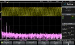
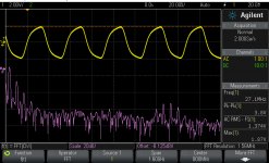
I found also that multichannel stage it work very well at 108Mhz clocking. The clock signal it is transmitted to the second DAC by the mean of some differential circuitry and line. All those devices involved in this clock transmission it support well this quite high clock frequency.
I was not before into the multichannels part of the player, and this stage it is not yet modified. Making some measurements, I can see that here the output offset difference between every single channel is quite big and with +/- levels just by chance (but in the mV range anyway). As I expected and expressed long time ago, this variation (in production process), explain why they chosen an AC coupling.
It is interesting that on (measured) FL/FR channels there is an +/-DC offset before the caps, but after those caps there still exist an equal 2mV positive offset on both those channels.
Another thing, the offset control for the I/V stages is independent of the rest of the system. While on the main board this is 1,650v, on multichannels board it is 1,000v. All the I/V resistors have identical value here.
The clock frequency of 108Mhz for the DAC it make the multichannels stage (in this case FR/FL) sounds quite good without any modification... But with a little bit lower dynamic, not so wide and detailed soundstage, while a very high fidelity...
What's eating you?
Contribute or don't. OK?
Sorry for say that, but I couldn't ever read something about a real contribution form this poster. Only expressed criticism for all and everything other come with in this forum...
From my part I choose to just ignore his interventions.
Well Coris,
I think we should give more credit to the engineers who create these devices that we buy.
The OPPO-105 is a technical tour de force.
The Panasonic plasma TV that I bought last year just astounds me with the images from Blu-ray.
Of course, these items are built to a price point, and consumers demand products at very low prices. It is this price pressure which produces the constraints that you have been studying in these products.
For those with the inclination, it also provides an opportunity to improve things…
- Home
- Source & Line
- Digital Source
- Oppo's BDP105 - discussions, upgrading, mods...