Low resistor on I/V continue....
I have experimented more accurate/systematic on this subject...
The goal is to find the best compromise when the residual HF noise from the DAC is minimum, reasonable offset on outputs, and no audible noise/hiss on speakers.
Some results here (with scope screenshots). Original I/V op amps and LM6172 as final. No any HF filtering on I/V, or further. Just straight signal path! DC coupling on outputs.
I have started (from an initial 750 ohm - x1 gain - ref voltage 2,2V, offset -0,5mV on outputs) with 330 ohm resistor on I/V and a gain on final of x3. I have no screenshots for this.
I've got an -1mV/-1,2mV (L/R) offset on outputs, I/V ref voltage = 1,4V. The residual HF noise is 130mV. Of course no any audible noise floor.
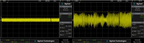
Next, lowered the I/V resistor to 75 ohm, and increase the gain to x12. The offset outputs goes to -2,9mV/-3,2mV (L/R) with a 0V reference voltage on I/V stage. I've got 46mV HF noise for accordingly usefully audio signal, as is to be seen in the picture.
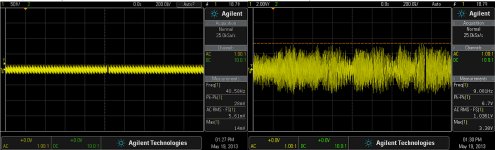
Next step, lowered the I/V resistor to 40 ohm with a gain of x22 on final. The offset on outputs increase to -4/-6mV for ref=0V. The HF noise get lower to 28mV for the outputted audio signal showed in the picture.
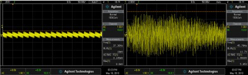
Last step, 20 ohm on I/V, and x75 gain (ref=0V). The offset on outputs get -10/-15mV (L/R), and the HF noise is now 18-20mV for a 11Vpp max audio out.
In all those steps I could not notice any audible noise floor on speakers. I have observed that with lowering the resistor on I/V, there is improvement in sound stage. Best for 20 ohm.
I could get lower with that resistor, but I just got tired this time... I have a feeling that the noise floor it will begin to rise with lowering further this resistor... But I will verify this one day...
With a resistor on I/V as recommended in Ess9018 datasheet (680 ohm) or even more to 750 ohm, the residual HF noise from DAC become hundreds of mV (500 -600mV), for an in may case, 12-15Vpp amplitude of useful signal and a x1 gain on final. In this case I had to use another procedure to lowered the HF noise to 32mV (no filter). As normal, one have to use filters to get rid of this quite high level HF noise on outputs...
I`m not decided yet which way to chose... but I think to take it the lowest resistor value one, or so.
Welcome to comments and opinion about those functional configurations here... Or maybe more/better results...
I have experimented more accurate/systematic on this subject...
The goal is to find the best compromise when the residual HF noise from the DAC is minimum, reasonable offset on outputs, and no audible noise/hiss on speakers.
Some results here (with scope screenshots). Original I/V op amps and LM6172 as final. No any HF filtering on I/V, or further. Just straight signal path! DC coupling on outputs.
I have started (from an initial 750 ohm - x1 gain - ref voltage 2,2V, offset -0,5mV on outputs) with 330 ohm resistor on I/V and a gain on final of x3. I have no screenshots for this.
I've got an -1mV/-1,2mV (L/R) offset on outputs, I/V ref voltage = 1,4V. The residual HF noise is 130mV. Of course no any audible noise floor.
Next, lowered the I/V resistor to 75 ohm, and increase the gain to x12. The offset outputs goes to -2,9mV/-3,2mV (L/R) with a 0V reference voltage on I/V stage. I've got 46mV HF noise for accordingly usefully audio signal, as is to be seen in the picture.
Next step, lowered the I/V resistor to 40 ohm with a gain of x22 on final. The offset on outputs increase to -4/-6mV for ref=0V. The HF noise get lower to 28mV for the outputted audio signal showed in the picture.
Last step, 20 ohm on I/V, and x75 gain (ref=0V). The offset on outputs get -10/-15mV (L/R), and the HF noise is now 18-20mV for a 11Vpp max audio out.
In all those steps I could not notice any audible noise floor on speakers. I have observed that with lowering the resistor on I/V, there is improvement in sound stage. Best for 20 ohm.
I could get lower with that resistor, but I just got tired this time... I have a feeling that the noise floor it will begin to rise with lowering further this resistor... But I will verify this one day...
With a resistor on I/V as recommended in Ess9018 datasheet (680 ohm) or even more to 750 ohm, the residual HF noise from DAC become hundreds of mV (500 -600mV), for an in may case, 12-15Vpp amplitude of useful signal and a x1 gain on final. In this case I had to use another procedure to lowered the HF noise to 32mV (no filter). As normal, one have to use filters to get rid of this quite high level HF noise on outputs...
I`m not decided yet which way to chose... but I think to take it the lowest resistor value one, or so.
Welcome to comments and opinion about those functional configurations here... Or maybe more/better results...
Attachments
Last edited:
That's quite interesting Coris, thanks for the measurements.
I am quite surprised by the excessive amount of noise you find.
It almost looks like the complete filtering of the DAC output has gone!
Basically there are three sources of noise that could play here:
1. The DAC noise - but knowing the ESS reputation I would expect that to be very, very small.
2. The noise from the I/V resistor.
I did a quick check with my old rule-of-thumb that 1k over 1 Hz gives 4nV, that would be about 600nV for 1 K over 20k bandwidth (multiply by quare root of BW). Even with a gain of 100 that would still be only 60uV!
3. The noise from the post-I/V amplifier. I guess you use an opamp here? I'm sure you selected a low-noise opamp (or use the opamp already present?). There's one more possibly cause - the resistors to set the opamp gain. The resistors also cause a noise which would be amplified by the opamp gain so that could explain the increase in noise with gian. What resistor values are used in setting those gains?
I don't know what's going on here but it is fishy.
BTW I looked at your scope plots, difficult to read the horizontal scale, is it 50m/s?
jan
BTW Did you check that the DAC is in current mode? If it still is in voltage mode, that can also explain some of the excess noise. I know the ESS can be used in both modes, but maybe that is fixed in the Oppo, don't know so this maybe a nonsense question.
Edit: Had a few friends over yesterday to show off my Oppo - they were suitably impressed ;-)
Last edited:
That noise you can see in my plots is high frequency (in Mhz range) residual noise which it came out from the DAC. This is normal, and its pattern, as one see in the pictures here, is also characteristic for ESS9018. This noise is to be filtered out by normal filtering stages placed in the signal path. As usually, the circuit designers place such filters into the I/V, between I/V and final and after final stage. Even though some designers use ferrite beads in the signal path to minimise this noise out on cables. But all those filters in my opinion affect quite much the quality of the resulting audio signal. There is huge difference when you hear the analogue out from the DAC with/without those filters. I chose to remove those filters. So, your observation that it may be no filtering in this case, is right.
Else, the noises you refer to, as I/V resistor noise or chip noises, are existing there in the pictures, but are extremely low comparing to this HF noise from the DAC....
The disadvantage of increasing audio signal quality (post DAC processing) is to have this HF noise out from the DAC at quite high levels. But those noises are not audible at all... Anyway is not very fortunate to have out on cables a such radio frequency in hundreds of mV... So one may find a way to not post filtering the audio signal, and in the same time get the lowest possible HF noise out of the box. It seems that using a lower value I/V resistor it is a benefit to reduce this HF noise.
It is my tring here in those above experiments, to find a solution to this issue...
PS. In one plot is about 50µ/s on horizontal. But here is more important what is on vertical scale.... The noise is measured at the output in absence of the useful (converted) audio signal.
As you may see in a earlier post here, Dustin (the designer of this chip) is describing what about this "current mode" of the DAC. It seems that people misunderstand a little this concept. In this case here, using a high value resistor for I/V stage it make the DAC work in "voltage mode". The opposite (lowering that resistor) it should "open" the current mode... But this aspect it still be discussed... I think that I understood right what Dustin try to explain in its (long time ago) intervention.
Last edited:
I have found the relevant posts; the Zout at each output appears to be 781 or so ohms. That explains why it can be used in voltage mode (high Z load) or current mode (low Z load). Very unusual, but apparently it works.
The disabling of the filtering is a personal judgement call - I would not do that, knowing what havoc these HF signals can wreak on the rest of my system, and I also am of the opinion that it detracts from the audio quality. But, as I said, personal judgement, to each his own.
Do you use the original opamp for I/V conversion, what type is it?
jan
Ahh the good old LM4562 - can't find anything wrong with that one!
BTW I still have problems with your scope shots. I'm pretty sure the horizontal scale is in 50mS per division, putting the noise square in the audio band, which I would expect anyway. It also corresponds with the mS vertical scale (same indication) and the frequency cursor.
Ohh well.
jan
BTW I still have problems with your scope shots. I'm pretty sure the horizontal scale is in 50mS per division, putting the noise square in the audio band, which I would expect anyway. It also corresponds with the mS vertical scale (same indication) and the frequency cursor.
Ohh well.
jan
Last edited:
Yes, is right. I double checked with a higher resolution plot. Is 50ms scale.
As you can see there is about high frequency bursts, and those have a lower frequency which is in low audio range. Even though is not possible to hear out of the speakers such residual noise, at that level.
As you can see there is about high frequency bursts, and those have a lower frequency which is in low audio range. Even though is not possible to hear out of the speakers such residual noise, at that level.
Just got a reply from Oppo about the crossover in the 105. The xover between the 'small' speakers and the sub is 12dB/oct. Which is pretty tame as xovers go.
I suggested a software update where the customer can select say 12, 18, 24 dB/oct slopes and, ideally, a few different filter types like Butherworth or Linkwitz/Riley.
That would allow people to chuck their active crossovers and just use the Oppo for that, and that can only be a Good Thing for Oppo!
But don't hold your breath")
jan
I suggested a software update where the customer can select say 12, 18, 24 dB/oct slopes and, ideally, a few different filter types like Butherworth or Linkwitz/Riley.
That would allow people to chuck their active crossovers and just use the Oppo for that, and that can only be a Good Thing for Oppo!
But don't hold your breath
jan
LM4562LM4562
Recommended for all Mod
He is really OP AMPS
thet ALL AROUND
I can agree that it is a good idea to have a such summarizing of the quite many mods of this player. From my part, I can not do it yet, because I'm still working.
At last this is not a very easy work/task, but if one will take this job it, based on what it were published here or in 95 thread, then I think it will be welcome...
At last this is not a very easy work/task, but if one will take this job it, based on what it were published here or in 95 thread, then I think it will be welcome...
LM4562
Recommended for all Mod
He is really OP AMPS
thet ALL AROUND
This chip is used in 105 (95 too). I will not say that is recommended, or the best, but I only answered to the earlier question about what Oppo used in the player.
in my mod on the audio circuit of the denon dvd 3910 i change all 10 op ampsThis chip is used in 105 (95 too). I will not say that is recommended, or the best, but I only answered to the earlier question about what Oppo used in the player.
to lm4562
the op amp is amazimg
A little tip is really starting to shine after a run of at least 150 hours
Some general considerations about DAC signal post processing...
I have to say that I have experimented a lot to find the best (almost at least...) way to process the converted audio signal out from the ESS9018. For sure, I'm not the only one who did this...
There are a very wide variety of op amps out there. Is very difficult to choose the best, without experimenting very much too. There is about here of opamps used in I/V stage and final. As I said many times, I do not want use filters in this post DAC processing. The impact of the filters is only positive in the theoretical side of signal processing. It looks good on the paper, on the scope, but is a disaster when is to listen it. Is my opinion.
It may be a benefit when about another DAC types, but ESS9018 can give a such high quality signal, that using filters on analogue it only to cancel the DAC high quality outputted signal.
I found out that those opamps it may be divided in three categories: There are opamps (no matter which high quality parameters or standard ones it may have), which place the resulting sound out of the system, into a imaginary line between the speakers. Not backward, not in front. The speakers are quite transparent in this configuration, but you hear all the instruments/voices concentrated on that imaginary line, only between the speakers.
There is another category op amps which realize a more wide soundstage, but in the background (back to the speakers). This time the listener hear the sounds in some sort as out of the room, placed on a imaginary arc between the speakers, in the back of those. The soundscene is better defined, the instruments/voices is possible to be localized on that imaginary arc, eventual in the center of it, but all it is happen back to the ( enough transparent) speakers.
There is another category of opamps and post DAC processing, which it bring a big part of the soundstage in to the front of speakers, as the rest is also in the back line of the speakers. The 3D sensation of the reproduced sound is very obvious, and the listener hear and can localize very precise the instruments/voices. The sound is just put it in front of the listener, it full out the room, and the speakers are completely transparent in the stage. One can hear and localize only the sounds, and is quite difficult to realize that are some speakers in the room. This is the best processing!
I have experienced this (also all those described here categories) when I worked on 95 model. I just found quite by chance the type of opamps which it could bring me the sounds in front of the speakers. There were not about very special parameters (or high) ones, but the resulting sound out of it, it were like described above. Unfortunately, I did not written down the names of that chips, I`ve got further to the next steps with my experiments and I lost the informations about such special result. I was very upset about this missing... and could never find again that configuration. Until now...
Also by chance I found the chips now in the last somewhere in a tray, in connection with the experimentations for 105 model. Now I`m very glad to find the best configuration for this DAC post processing analogue signal, to get such fantastic result.
There is about some J-FET opamps, which as I said before, it not have very special high parameters. I use 20 ohm for I/V stage and LM 6172 for final. Because of better amplification in HF frequency from the I/V opamps, I get a little bit higher residual HF noise (38mV) on RCAs. The offset it can be adjustable in my system, so I can get the same offset on L/R (-8mV). I think this is very reasonable to further use DC coupling.
Now it may be the time to just go further to the next steps/mods on 105...
Last edited:
Coris:
Could you please clarify one point? Does your value of 20 ohms for I/V conversion (which you mention above) correspond to the value of the resistor that you are using for passive I/V conversion (along the lines of what Joe is doing), or is this the value of the feedback resistor which you are using inside of an op-amp based I/V circuit?
Could you please clarify one point? Does your value of 20 ohms for I/V conversion (which you mention above) correspond to the value of the resistor that you are using for passive I/V conversion (along the lines of what Joe is doing), or is this the value of the feedback resistor which you are using inside of an op-amp based I/V circuit?
Last edited:
There is not about passive I/V here. This 20 ohm resistor it is so called "the feedback" resistor of the I/V op amp. I will not name that "feedback", because that resistor is actually the resistor which make the conversion current - voltage. This resistor is to be seen (AC point of view) on the DAC current output, and at the op amp input, which op amp will further process the resulting voltage on it.
But anyway, this resistor is mounted as in the feedback of the I/V op amp.
BTW, now is my turn to have a question, maybe for Joe.
I have seen that it is necessary a very high gain to compensate the use of such low I/V resistor. In my experiment with active I/V, when I used 5 ohm resistor, I had to increase the gain on final stage to x300, to have a reasonable output level. Then the noise floor increased too in the system.
I just wonder what about this noise floor level, when one use 3 ohm paralleled with a quite low impedance transformer coil. The resulting signal level it may be very low at the output of that transformer, and the gain to amplify this low level signal in the next stage it may be very high. What about the noise in such configuration?
Last edited:
Sorry for say that, but I couldn't ever read something about a real contribution form this poster. Only expressed criticism for all and everything other come with in this forum...
From my part I choose to just ignore his interventions.
haha, no its not criticism of you, its criticism of your utter disregard for techniques that can guide proper experimentation and proven results, rather than fumbling in the dark, making guesses at what to do.
making it your mission to deliberately ignore proper techniques and substitute your own magic, like connecting SMD decoupling caps with flying wires and thinking you have to multiply everything, it makes no sense. increase capacitance by 1000x what it should be instead of tackling noise at the source, increase clock speed massively when you mainly play 44.1, increase the voltage gain when you already have more than enough, increase the regulator voltages to get better performance when you havent made the most of regular voltages.
if you were really looking for improvements instead of futsing about, you might be interested to see if there really are improvements. here with the video we have an example where it is easy to prove one way or the other, but predictably, you would rather just take the lazy way and simply state 'huge improvements in everything' and avoid the possibility of exposing an error in judgement.
just like every other thing you post, you are always claiming improvements based on 100% subjective response and assumptions or superstition. You refuse even doing pure listening tests or visual comparisons, but rather based on your memory of before the mods and coloured by your bias, like you are some sort of super human that somehow remembers things that accurately and isnt effected by bias.
subjective testing is a powerful tool, but it cannot take the place of objective testing, you need both and you certainly need both if you take on an area you know nothing about. Digital video processing bandwidth is well outside any possible human senses. you really expect people to sit by while you just start poking at things and claiming you have better skills than the engineers immediately, with nothing at all to back your statements up? if you were working in the business, you could have been taken to court multiple times.
youve been modding these things for years and dont seem to have progressed past these same ways, the mods all look the same as back then, people ask you about what to do to their machines because you have posted so much about them. If you are going to do that, you have a responsibility to do things properly and if you wont, but continue to promote this sorcery, I will continue to be here to provide some perspective every now and then
extraordinary claims require extraordinary evidence.
especially when making claims that are contrary to large bodies of evidence
I normally let most of your handwaving slide btw you really think I correct everything you say?
Last edited:
Let it go qusp.
Took me several pages to realise that what he calls 'I/V resistor' is just the feedback resistor rather than the output load on the DAC.
But because the fashion is to be against feedback, you need to 'invent' a reason not to call it feedback. And then totally misapply that resistor value because total ignorance of the circuit issues, in the process destroying a pretty good player back to the 60dB S/N of the avarage kitchen radio and claiming fantastic dynamics!
Its so bad here it isn't even wrong.
But it's people's own responsibility; you can lead a horse to water but you can't force it to drink.
jan
- Home
- Source & Line
- Digital Source
- Oppo's BDP105 - discussions, upgrading, mods...