Let me repeat, and remind you that Salas told you before.
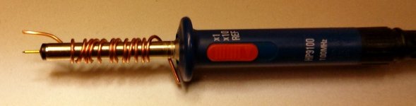
YOU HAVE ABSOLUTELY NO CHANCE of showing on the oscilloscope any signal that is at a level of 300uV peak-to-peak UNLESS you have your oscilloscope probe like the attached picture. The shunt regulator, when it works the way it should, does not have voltage ripple above at most 500uV p-p!!!
A few centimeters of ground wire will add to the noise and it will show above 1mV ripple. A probe like the one in the attached image is NOT OPTIONAL, IT IS A MUST!
Once and for all you have to accept this as absolute truth!") I'm serious.
I'm serious.
YOU HAVE ABSOLUTELY NO CHANCE of showing on the oscilloscope any signal that is at a level of 300uV peak-to-peak UNLESS you have your oscilloscope probe like the attached picture. The shunt regulator, when it works the way it should, does not have voltage ripple above at most 500uV p-p!!!
A few centimeters of ground wire will add to the noise and it will show above 1mV ripple. A probe like the one in the attached image is NOT OPTIONAL, IT IS A MUST!
Once and for all you have to accept this as absolute truth!
I'm serious.Attachments
Wopsie. There came some serious stuff. Thanks Iko. This time althoug my interest was not to determine the exact uV ripple from the SSHVs, mere just to search if the 50 Hz problem was there. Apperantly not so far.
And for us other wayfarers, heres some sample of todays excavations.
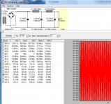
What does 0,090 and 0,045 mean? Is that relevant figures?
And for us other wayfarers, heres some sample of todays excavations.
What does 0,090 and 0,045 mean? Is that relevant figures?
Attachments
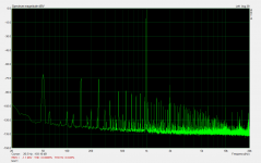
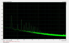
Its the targeted THD related to 1kHz test tone (2kHz, 3kHz etc) and then +N(oise). You got a nicely low second harmonic 2kHz at -80dB relative to 1V output but the many high harmonic noise spikes up the average unfortunately. I.e. load line not bad, hum&buzz bad.What does 0,090 and 0,045 mean? Is that relevant figures?
Its the targeted THD related to 1kHz test tone (2kHz, 3kHz etc) and then +N(oise). You got a nicely low second harmonic 2kHz at -80dB relative to 1V output but the many high harmonic noise spikes up the average unfortunately. I.e. load line not bad, hum&buzz bad.
"If you cant explain it simply, you dont understand it properly." AA. I just waited for it, thanks!
So while Im puting for Ikos measure here, whats the local poll:
What would be your first shot?
- fiddling filaments
- finding op points with B+
- decoupling chokes with a small zobel
Setting the op point for the tube first.
Then you test some different tubes.
When you find a nice pair finetune the filaments.
If you look at that picture, you will see that the spike at 50Hz is somewhere around -53dB. Let's assume this is relative to 0dB = 1V. To calculate how many volts -53dB is relative to 1V, you do 10^(-53/20) = 2.2mV. So, at 50hZ you have a ripple of about 2.2mV RMS = 2.2*sqrt(2)*2 = 6.22mV p-p. In Arta you can click the mouse on the spike and then use the lef-right arrow buttons on the keyboard to measure more precisely how many dB the spike is at its highest point. You can calculate like this the mV value of the ripple for the other harmonics as well, 100hZ, 150hZ, etc.
Suffice to say, you have more ripple than what you should have from the HV shunt regulator.
Suffice to say, you have more ripple than what you should have from the HV shunt regulator.
That FFT is on the audio output. It represents everything circuit in there. Why is it just rail ripple? Where was that ripple on the rail scope test? Hum is 50Hz ripple is 100Hz. But 100Hz is -90dB there. The spray of harmonic noise is too wide to be just ripple on the rail of a buffer at line level IMHO. If feeding B+ with just CRC I am not sure that the picture would change much. And such a test could easily eliminate rail related questions or point at the PSU side indeed so to move on investigating. I would bet more on oscillation of the reg on the choke than just ripple if it is coming from the rail. There is suspicious microphony reported also, I would investigate instability or loop area issues regarding the choke loading next.
Start with a basic resistor load and get the thing up and running properly first.
Chokes have a nasty habit of picking upp every unwanted signal there is.
Split the PSU from the amp getting rid of any AC near the amp.
I´ve got nice shielded industríal power cables come and get them Stajo.
After that you can start investigating the amp for grounding and stability issues.
Now there´s so many factors involved .
.
Chokes have a nasty habit of picking upp every unwanted signal there is.
Split the PSU from the amp getting rid of any AC near the amp.
I´ve got nice shielded industríal power cables come and get them Stajo.
After that you can start investigating the amp for grounding and stability issues.
Now there´s so many factors involved
.Howdy. Its a kind of holliday here and I woke up early so what to do if not play around with new scope.
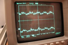
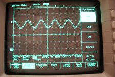
Yesterday I made a conversion of the choke loaded CF to a resistor loaded and listened and measured. (Pic 1) About the same looking Arta curves and a small hum plus audiable noice in speakers. I also tried to feed it directly from PSU filter, without SSHVs. Small differences regarding hum and noice but the 305 V on the anodes sure made music glare.
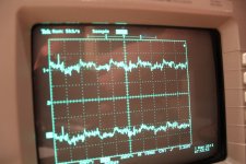
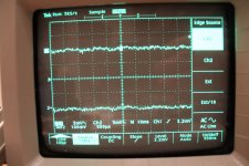
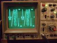
So, today I made some scoping on the power rails. First up is PSU filter on 13,5 k/channel dummyload. (Pic 2). Around 5 mV p-p (1,8 mV rms) which I think is to much for this config. Should be less if the measuring tools doesnt add something.
I made a sim in PSUD II that says 127 uV (Pic 3)
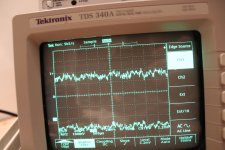
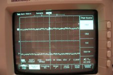
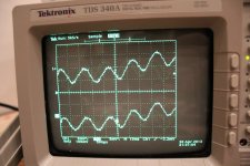
Then I set the SSHVs on same dummyload (Pic 4). 5 mV/div so now we are down to measuring tolerances but occasionally I also noticed small occational spikes on the scopescreen. Very hard to catch on camera but you can see a shadow on Pic 5. Then a view on the same with 2 mV/div (Pic 6).
For some reason SSHV V in looks more stable then when the bare PSU loads a resistor dummyload (pic 7).
After that I removed dummyload and plugged in the reconverted choke loaded audio circuit. Pic 8 on the anodes, 2 mV/div, and Pic 9 on cathodes.
I guess this takes a coffee, some reference measuring and more
Yesterday I made a conversion of the choke loaded CF to a resistor loaded and listened and measured. (Pic 1) About the same looking Arta curves and a small hum plus audiable noice in speakers. I also tried to feed it directly from PSU filter, without SSHVs. Small differences regarding hum and noice but the 305 V on the anodes sure made music glare.
So, today I made some scoping on the power rails. First up is PSU filter on 13,5 k/channel dummyload. (Pic 2). Around 5 mV p-p (1,8 mV rms) which I think is to much for this config. Should be less if the measuring tools doesnt add something.
I made a sim in PSUD II that says 127 uV (Pic 3)
Then I set the SSHVs on same dummyload (Pic 4). 5 mV/div so now we are down to measuring tolerances but occasionally I also noticed small occational spikes on the scopescreen. Very hard to catch on camera but you can see a shadow on Pic 5. Then a view on the same with 2 mV/div (Pic 6).
For some reason SSHV V in looks more stable then when the bare PSU loads a resistor dummyload (pic 7).
After that I removed dummyload and plugged in the reconverted choke loaded audio circuit. Pic 8 on the anodes, 2 mV/div, and Pic 9 on cathodes.
I guess this takes a coffee, some reference measuring and more
Attachments
-
 scope 6V6 019 (3000x2000).jpg690.2 KB · Views: 86
 -
 scope 6V6 018 (3000x2000).jpg695.1 KB · Views: 83
 -
 scope 6V6 017 (3000x2000).jpg740.1 KB · Views: 79
 -
 scope 6V6 015 (3000x2000).jpg695.3 KB · Views: 95
 -
 scope 6V6 010 (3000x2000).jpg696.5 KB · Views: 274
 -
 scope 6V6 009 (3000x2000).jpg662.1 KB · Views: 288
 -
 PSUD (725x685).jpg143 KB · Views: 305
 -
 scope 6V6 003 (3000x2000).jpg763.6 KB · Views: 339
 -
 scope 6V6 001 (3000x2000).jpg873.8 KB · Views: 358
- Home
- Amplifiers
- Tubes / Valves
- 6V6 line preamp