Cbe is indicative, not critical: during normal operation with bias applied, it should be swamped by the diffusion capacitance.So, what this mean? Is Cbe a critical value for bias servo here? Do we consider that BD140 ones obviously out of spec?
It could begin to cause troubles only if it is way excessive.
By contrast, Ccb is always important
In this case, a 25% difference is just that. You decide whether 25% is a big difference or not. I would worry if it was around 100% (doubled) or so.
645pF for a C5171 would indicate a counterfeit! Compare the values you find to the SPICE model values, which are specified at 0V bias.
645pF for a C5171 would indicate a counterfeit! Compare the values you find to the SPICE model values, which are specified at 0V bias.
Last edited:
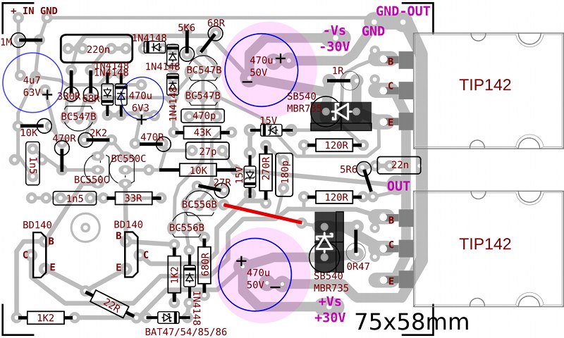
Terranigma, I need some help with the documentation for it.I consider that I finished my PCB layout of N-Darlington output version of vanilla Circlophone. I built two channels and they are running for a while. Purity, dynamics, punchy bass.. I think this version is no less than original output scheme. Even with those ST TIP142's. . . .I used BD140's as servo transistors because mine were good quality ones from Philips and Harris. I measured their cb capacitance at 0V and Harris ones were always lower (35pf vs 52pf).
Unobtainium parts reliance issues: So, not a random BD140, but rather a little "super driver" sort with fine specs. Neither the Harris nor the Philips are widely available. I wonder what we can find for substitute at Mouser, Digikey, etc. . . Perhaps Fairchild has something for us? We need to list something with higher availability, for the documentation.
Other than the unobtanium vas, this version looks fantastic because it is the easiest and most compact way to build a Circlophone.
Given the 30+30vdc (60v) operating voltage and unregulated power (surges happen) we might need to list something other than BC556B (maxed at 60V) in the sensor area.
So, basically, we need an updated photo that lists alternate transistors for vas and sensor, in order to assure expected operation on all builds.
P.S.
Have you tried replacing the zener with transistor, per Elvee's post#1151 above?
Last edited:
Terranigma, I need some help with the documentation for it.
Unobtainium parts reliance issues: So, not a random BD140, but rather a little "super driver" sort with fine specs. Neither the Harris nor the Philips are widely available. I wonder what we can find for substitute at Mouser, Digikey, etc. . . Perhaps Fairchild has something for us? We need to list something with higher availability, for the documentation.
I also tested 2SA1220 (Nec), 2N5401, 2N2905A in place of BD's during tracing overshoot behavior. Actually I couldn't manage any difference between their behavior with oscilloscope. I showed BD140 part on layout because I consider that builder is aware of NOT to choose a random BD device. If I could find a 2sa1360 (2.5pf Cob) from a local store maybe it is going to be shown in the layout. It would be a good candidate for higher supply voltage usage. It is very easy to adapt mounting holes for 8-10pf capacitors between c-b legs of servo transistors in current layout. Maybe these self compensation caps aren't going to be necessary. I can't be sure until test it on real circuit.
Other than the unobtanium vas, this version looks fantastic because it is the easiest and most compact way to build a Circlophone.
Given the 30+30vdc (60v) operating voltage and unregulated power (surges happen) we might need to list something other than BC556B (maxed at 60V) in the sensor area.
KSA922, 2SA970, 2N5401 (and their couples) are suitable for sensors in higher supply voltage usage and they are easily attainable. Transistor leg arrangement must have considered in this case.
So, basically, we need an updated photo that lists alternate transistors for vas and sensor, in order to assure expected operation on all builds.
No problem.
P.S.
Have you tried replacing the zener with transistor, per Elvee's post#1151 above?
I consider it must be applied as shown in Elvee's jfet buffered schematic at post #637 (but using a PNP device?) If so, it is possible to alter zeners with a single transistor without altering layout. Not an artistic way but it is doable at least.
Attachments

Last edited:
I consider it must be applied as shown in Elvee's jfet buffered schematic at post #637 (but using a PNP device?) If so, it is possible to alter zeners with a single transistor without altering layout. Not an artistic way but it is doable at least.
I just realized that layout must have altered due to compensation network placement according to schematic.
Ah, not good sounding to use the speaker output as the reference point; however. . .
I assume that should sound very similar to using the zeners, except with the convenient automation of a transistor instead of buying voltage specific zeners.If you want to mimic more closely the effect of zener with a transistor, you can tie its base to the ground instead of the output.
Last edited:
Elvee, it seems, your private message limit reached.
In case of inverting whole layout of my darlington setup but not to come down a pnp transistor as output, then I need a pnp-npn mixed darlington pair. If I understand correctly, your suggestion is complementary darlingtons like TIP121/27 , BDX53/54. Do you mean Sziklai pair? Is there something like Sziklai pair in one package?
http://www.onsemi.cn/pub_link/Collateral/MJH11017-D.PDF
Last edited:
I gave examples of complementary darlingtons to show that there is little difference (in print) between the P and the N.Ok I understand... If using complementary type of darlingtons (not sziklai in one package) there should be nothing to worry too much. I'm a bit confused with definition of "complementary".
Of course, in an amplifier you only use one variety, P or N, not a mix.
Harris BD140, the search continues. . .
Question: What is the lower voltage version of KSA1220?
In 1988 Intersil was taken over by Harris Semiconductor (Intersil's new parent company). In 2001, Intersil's discrete transistor business was purchased by Fairchild Semiconductor. Today, the Harris BD140 (a high end part) probably has a new Fairchild model number, not a BD140.
Last edited:
Mosfet output and R21 current
During simulating jfet as CCS instead of R2 (R21 in original schematic) I noticed that ~7-7.5 mA CCS (~8.2K) decreases THD to 0.0004 levels. I don't know that it is realistic or not but it is good to have your opinion on this observation. I doesn't happen with standard version. Darlington version doesn't affect that much.
During simulating jfet as CCS instead of R2 (R21 in original schematic) I noticed that ~7-7.5 mA CCS (~8.2K) decreases THD to 0.0004 levels. I don't know that it is realistic or not but it is good to have your opinion on this observation. I doesn't happen with standard version. Darlington version doesn't affect that much.
Attachments
Last edited:
Normal: the current is so high it overwhelms the common mode servo, forcing operation in class A with a quiescent current in excess of 5.5ADuring simulating jfet as CCS instead of R2 (R21 in original schematic) I noticed that ~7-7.5 mA CCS (~8.2K) decreases THD to 0.0004 levels. I don't know that it is realistic or not but it is good to have your opinion on this observation.

No surprise it results in lower THD: feel the heat guvn'r, that's the real stuff
Normal: the current is so high it overwhelms the common mode servo, forcing operation in class A with a quiescent current in excess of 5.5A
No surprise it results in lower THD: feel the heat guvn'r, that's the real stuff
Which means amplifier is not a Circlophone anymore? With mosfet output, is it worth to slight increase of current? Or is it just matter of how much we dare to deal with heat issues?
No, one of the loops is disabled.Which means amplifier is not a Circlophone anymore?
You can investigate, using "proper" means: like reducing R6 and R8 for exampleWith mosfet output, is it worth to slight increase of current?
Error: Schematic at post 1172 has referenced "zener replacement transistor" base to AC; so, please change that to reference base to ground instead of the biggest noise available. No need to pollute the feedback loop either. Egads, that's bad!  Dreadful audio quality! Just don't do that. At this point I'm extremely sorry that I mentioned the transistor. Looked convenient, but it is not.
You can improve your audio quality by re-installing the zeners, or. . .
Nice smooth flat ground. So much better.
. . . or bring back the zeners.
Dreadful audio quality! Just don't do that. At this point I'm extremely sorry that I mentioned the transistor. Looked convenient, but it is not. You can improve your audio quality by re-installing the zeners, or. . .
Yeah! Like that!Elvee said:If you want to mimic more closely the effect of zener with a transistor, you can tie its base to the ground instead of the output.
Nice smooth flat ground. So much better.
. . . or bring back the zeners.
Last edited:
Error: Schematic at post 1172 has referenced "zener replacement transistor" base to AC; so, please change that to reference base to ground...
That was just for simulation purpose. I considered your opinion already. Let's think about a simple 1-1.5 mA universal CCS solution. Current Regulator Diodes are not common these days and they are not that cheap.
Circlophone with mosfets + CCS + DCoffset
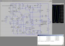
This is what I had integrated in my version of Circlophone (in simulation only).
It is a combinatio n of a lot of the suggestions made by Elvee, and a few deviations of his advice.
It is bit of a special version because it is to drive an electrostatic speaker through a step-up transformer. In the end his proposal to put a elco between the output and the trafo solved the saturation problem of the transformer but was (in simulation) a cause of distortion.
His alternative to create a DC offset circuit takes care of this.
This version is with MOSFET's as output device. The model is slightly adapted following some guidelines of Bob Cordell for the transition regio.
Some other smalle modifications were integrated to keep everything under control. The only thing that I cannot solve (don't know if it is a problem) is with squarewave exitation of higher inputvoltage and frequenty, there is still an offset.
I would like to ask Elvee to have a look at this version to see if this could be a viable solutions for a high power version. Since the MOSFET's seem to have a large SOA (520 Watt/200V) I hope it's possible to do withouth speaker protection (since there are no sensitive tweeters at the output).
I hope that the limitation of the output divices can be achieved by the limitation of the supply and transformer.
Supply voltage is limited to 38 Volts, iddle power in outputdevices is 31Watt.
(rather high, but I have 2 heathsinks of 0.34 °C/watt available). So total iddle dissipation is +/1 65Watt per channel.
I have noticed that the output voltage is not equaly formed by the 2 output FET's. So I'm wondering if it should be necessary to try to match the 2 MOSFETS ?
Thanks for looking,
R21 CCS? Yes sir. The following 3 options are made by Elvee, to fit standard Circlophone.
From left to right: Resistor option, simple CCS, advanced CCS
This is what I had integrated in my version of Circlophone (in simulation only).
It is a combinatio n of a lot of the suggestions made by Elvee, and a few deviations of his advice.
It is bit of a special version because it is to drive an electrostatic speaker through a step-up transformer. In the end his proposal to put a elco between the output and the trafo solved the saturation problem of the transformer but was (in simulation) a cause of distortion.
His alternative to create a DC offset circuit takes care of this.
This version is with MOSFET's as output device. The model is slightly adapted following some guidelines of Bob Cordell for the transition regio.
Some other smalle modifications were integrated to keep everything under control. The only thing that I cannot solve (don't know if it is a problem) is with squarewave exitation of higher inputvoltage and frequenty, there is still an offset.
I would like to ask Elvee to have a look at this version to see if this could be a viable solutions for a high power version. Since the MOSFET's seem to have a large SOA (520 Watt/200V) I hope it's possible to do withouth speaker protection (since there are no sensitive tweeters at the output).
I hope that the limitation of the output divices can be achieved by the limitation of the supply and transformer.
Supply voltage is limited to 38 Volts, iddle power in outputdevices is 31Watt.
(rather high, but I have 2 heathsinks of 0.34 °C/watt available). So total iddle dissipation is +/1 65Watt per channel.
I have noticed that the output voltage is not equaly formed by the 2 output FET's. So I'm wondering if it should be necessary to try to match the 2 MOSFETS ?
Thanks for looking,
Attachments
- Home
- Amplifiers
- Solid State
- ♫♪ My little cheap Circlophone© ♫♪