Am I missing something? I don't see any Mos version in the zipThis version is with MOSFET's as output device.
With squarewave, there is often a problem of initial conditions leading to a large offset for a long time.Some other smalle modifications were integrated to keep everything under control. The only thing that I cannot solve (don't know if it is a problem) is with squarewave exitation of higher inputvoltage and frequenty, there is still an offset.
Alternatively, if the slew rates are asymetrical, it can create a small offset, wich is normally not a problem, but could be an issue with a transformer.
This type of output stage uses the "virtual complements" concept, meaning symetry is as important as for a conventional amplifier.I have noticed that the output voltage is not equaly formed by the 2 output FET's. So I'm wondering if it should be necessary to try to match the 2 MOSFETS ?
Probably more important in the case of MOS, since the dispersion is much larger than in Bjt's
Am I missing something? I don't see any Mos version in the zip
/QUOTE]
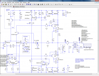
The output transistors are IRFP4668 Power Mosfet.
I included the model in the text.
Edwin
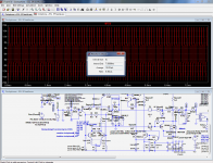
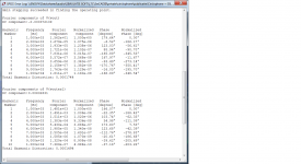
Here is what I find:
Your right (as always).

This is indeed an old test. Sorry for this.
I hope this time I will be able to complete the simple task off uploading the correct file.
Edwin
Attachments
The diode models having a suffix _C are not included in any of the zips.
There is also a call to a non-existent zetex_models library
The zetex lib is not used (I used to test some transistor in sim for the Q5/Q6 but it made little difference. The diode model is now included. I missed this while cleaning up my testfile.
I hope all is included now.
I should mention that here and there there are parasitic elements included in the elements to try to find out if the simulation is sensitive to these elements.
Thanks for looking.
Attachments
I have used alternative diodes to replace the missing ones, and replaced the sine source on the squarewave node by a squarewave, but I notice no particular offset problem.
If you want to highlight a particular problem, you should save a version parametrized for that situation, as it is difficult to guess which parameters exactly you have to alter to show the problem without spending hours analyzing every detail.
If you want to highlight a particular problem, you should save a version parametrized for that situation, as it is difficult to guess which parameters exactly you have to alter to show the problem without spending hours analyzing every detail.
Attachments
I have used alternative diodes to replace the missing ones, and replaced the sine source on the squarewave node by a squarewave, but I notice no particular offset problem.
If you want to highlight a particular problem, you should save a version parametrized for that situation, as it is difficult to guess which parameters exactly you have to alter to show the problem without spending hours analyzing every detail.
Ok, fair enough.
I included the model for the diode I missed the last time (always happens when doing something in a hurry).
To make things clear, I just wanted to know if the modifications) I made are reasonable. They were tested to try to improve the distortion figures. In some of the early variations I noticed sometimes a small oscillation at intermediate levels. They have disappeared.
I was at the time trying to replicate all the variations that were discussed.
After you mentioned that NMos works but with worse distortion, I tried some variations and came to this schema. I just noticed that my schematic is different from the one in post 62. I will point out that R9 and R12 are made unequal.
Distortion in my sim was most dependent on output transistor, bias level, but also on the type of power diodes although you mentioned somewhere along the line this is not critical. This could be caused by inadequate models. I the schematic I included two parallel diodes with the parameters I found by the manufacturer. The diodes are already paralleled in the same package. I'm not sure if this is the correct way to use them in simulation (couldn't find any info on this).
Further improvements come from replacing the servo resistor by a ccs( as you suggested), and raising the supply voltage. A further improvement I got was by doubling the drivers Q9/Q11 with a second one in parallel, but I doubt it's the trouble.
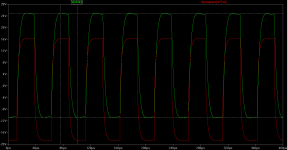
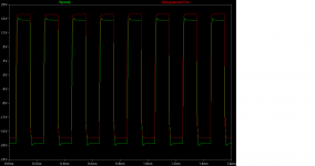
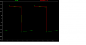
About the square wave I don't know if it is a problem, I just mentioned it because I found it strange and don't know if it is a real behavior or an anomaly of the simulator. I include some results to show how the output shifts (200Hz, 5 KHz end 20 KHz). When I checked this just now I see that even the input voltage has a small shift (red trace= input voltage x gain, green trace= output to Transformer for ESL). Real music will in reality not contain much square waves, but I suppose an amp must be capable to reproduce all signals (within reason).
If all those modifications are not causing troubles and could improve the behavior in reality, I would like to try to build it. The layout of the PCB will become more important if the improvements of distortion are to be attained in reality.
Edwin
Attachments
A number of diode models are still missing, plus a file that it tries to include, but some things can already be said: the effect of the diodes should be minimal, their presence being required mainly for energetic efficiency reasons.
If they have a significant impact on the quality, that means something is not working properly.
I think the circlophone circuit is partially paralyzed, because with the high Iq you indicate on the schematic, the upper diode must always conduct and this prevents the servo from operating normally.
If they have a significant impact on the quality, that means something is not working properly.
I think the circlophone circuit is partially paralyzed, because with the high Iq you indicate on the schematic, the upper diode must always conduct and this prevents the servo from operating normally.
I have revised the layout posted by Alex to include a film input capacitor, and also changed areas that were congested, added pads for TO-XXX case transistors for the VAS, and routed new traces to the ground star to keep signal, power supply decoupling, and zobel network returns separated. I would like to upload the .LAY file for editing and printing with Sprint Layout 5, but DIY audio forum file upload says it's an "invalid file type". If anyone is interested, suggest a workaround to uploading files... If nothing else, I can try to create a PDF instead.
Hi! spare_parts,
I would be very glad to have a copy of *.lay file, I am also a Sprint user.
Kindly send a copy to aco.ocampo@gmail.com.
Thank You!
I would be very glad to have a copy of *.lay file, I am also a Sprint user.
Kindly send a copy to aco.ocampo@gmail.com.
Thank You!
Try to "disguise" it by adding a .txt suffix after the .lay, and if it doesn't work, put it in a zip.I would like to upload the .LAY file for editing and printing with Sprint Layout 5, but DIY audio forum file upload says it's an "invalid file type". If anyone is interested, suggest a workaround to uploading files... If nothing else, I can try to create a PDF instead.
Also changed diode packages to TO-220
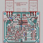
In my opinion those diodes must have thicker tracks at both side. Almost all current drawn by output transistors passes through these diodes. The diode at positive rail has more current swing but donated with signal level thickness track. You can do fine with only one resistors each side (1R and 0.47R), thus able to place more room for thicker tracks. Also, I would prefer to place those diodes closer to the power transistors rather than resistors.
Last edited:
This is much better!agreed, was looking at that also... changes added one jumper.
Regards!
agreed, was looking at that also... changes added one jumper.
Much better. Hope you don't forget to fix resistor values. Other things that I would consider:
* Bypass caps may be better to place to other side of fuses. Bypass caps can help for recovering nonlinear behavior of fuses if they have placed front of fuses.
* Just an idea: TO-3 metal case transistors can be fitted as an option on same layout (or alternative layout). I was working on such kind of a layout by considering Carlos' Dx super A layout's output section. You can refer to this link: http://www.diyaudio.com/forums/solid-state/221741-dx-blame-st-together-dx-super-75.html#post3446208
Last edited:
Hi All!
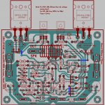
I did my own version of the original AlexMM lay-out for the original Circlophone, lay files courtesy of spare_parts. I have eliminated the TO-39 for VAS, (this package is becoming harder to find here in my place) instead I replaced them with TO-126 type and I managed to allow a small space for a DIY heatsink on VAS. Also I made sure that I have inserted the missing 470pf on the original lay-out, replaced the smoothing capacitors with a single one and omitted the LED indicators just for simplicity of the design. I have wanted the board to become smaller in size but further modification restricts parts movement.
In case anyone will find the lay-out useful, here it is.
Thank You!
Attachments
Hi All, (again  )
)
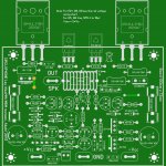
I just thought that following the basic elements is simply wonderful, this new lay-out is my preference. Experience suggests that a wider space for VAS heat sink is necessary and I have always read that an output coil is becoming necessary for an amp, this is the only addition not indicated in the basic schematic. Surprisingly the whole board is only a few inches bigger than Powerflux design.
Any comments is very much welcome.
Thank You!
)I just thought that following the basic elements is simply wonderful, this new lay-out is my preference. Experience suggests that a wider space for VAS heat sink is necessary and I have always read that an output coil is becoming necessary for an amp, this is the only addition not indicated in the basic schematic. Surprisingly the whole board is only a few inches bigger than Powerflux design.
Any comments is very much welcome.
Thank You!
Attachments
- Home
- Amplifiers
- Solid State
- ♫♪ My little cheap Circlophone© ♫♪