Tony
Have you taken into account the fact that the o/p inductance of the LM317 reduces significantly as Iout increases? I think Erol Dietz's measurements of resonant frequencies were for a datasheet implementation of the LM317 circuit with 5mA or 10mA Iout, but doesn't your circuit have a larger Iout and therefore a lower o/p inductance?
Actually Dietz' paper covers this as well

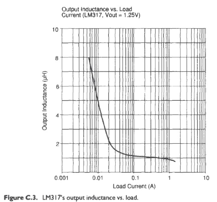
- so beyond about c. 50mA I'd expect very little change in the modelling ( - as I posted above)
NOTE - this graph is at 1.25v out, i.e no 'lower' R to 0v for voltage setting. That means the graph only holds if you use the optional Cadj bypass cap at higher voltage outputs (Yes, using this cap drops the effective output inductance at higher voltage output. Obvious once you think about what it does)
I have sometimes deliberately added power resistors to '317 regged supplies to push the total draw toward or well past that 30-50mA mark - on low-demand items when the raw supply / heatsinking will comfortably support it. Sometimes it seems to help by measurement, even audition.
Similar things are true of more complex regulators, too: it seems mostly to do with re' and beta in the output pass transistor IME.
Last edited:
Dumb question: when putting this resistor in series with the output capacitor to damp any resonance, do we have to care about its wattage rating?
For example, for a 9V output voltage in series with a 1uF polyester capacitor, and a 1Ω resistor in series with it, what is the minimum wattage rating?
On DC conditions, it shall not dissipate power I suppose.
For example, for a 9V output voltage in series with a 1uF polyester capacitor, and a 1Ω resistor in series with it, what is the minimum wattage rating?
On DC conditions, it shall not dissipate power I suppose.
On DC conditions, it shall not dissipate power I suppose.
correct
1/4 watt should be more than enough! It is only really noise that is going to be being passed to ground via the cap, and hopefully this is already at a very low level due to the regI ran the sim of my reg circuit with a 600mA current source as the load and the power dissipated in the resistor (in the case of the sim a 0.5 ohm and cap was 100uF) was 270 pico watts. I believe that this is from the residual ripple still present on the output.
With a real (varying) load this may change a little but I don't think you are going to see any significant power being dissipated in this resistor. I actually used some small SMD resistors in this place.
edit: I re-ran the sim with 1uF and 1 ohm and the power dissipated in the resistor dropped to 56 fempto watts. I guess since the residual noise is 100Hz and it's harmonics that 1uF is going to struggle to do much about it.
Tony.
Last edited:
Seems quite right! The 1uF cap is a bit small for anything severe to pass.
I will try a 1/4 watt metal film then!
I will also add a 100u cap on the output, in parallel with the RC series network.
I assume that this is not going to ruin the damping I will aply using the 2R7, am I right?
I will try a 1/4 watt metal film then!
I will also add a 100u cap on the output, in parallel with the RC series network.
I assume that this is not going to ruin the damping I will aply using the 2R7, am I right?
Not exactly. If you put a low esr 100uF cap in parallel with the 1uf then it will still have a resonant peak, it will be lower in magnitude and shifted down in frequency though.
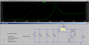
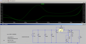
On simming the 1uF with 2.7 ohms in series even that apears to give quite a peak. 100uF with 0.7 ohms in series seems to be a much better option.
edit: that last one I forgot to put in some inductance in the 100uF cap so it does not show the rising impedance with frequency.
Tony.
On simming the 1uF with 2.7 ohms in series even that apears to give quite a peak. 100uF with 0.7 ohms in series seems to be a much better option.
edit: that last one I forgot to put in some inductance in the 100uF cap so it does not show the rising impedance with frequency.
Tony.
Attachments
Not exactly. If you put a low esr 100uF cap in parallel with the 1uf then it will still have a resonant peak, it will be lower in magnitude and shifted down in frequency though.
On simming the 1uF with 2.7 ohms in series even that apears to give quite a peak. 100uF with 0.7 ohms in series seems to be a much better option.
edit: that last one I forgot to put in some inductance in the 100uF cap so it does not show the rising impedance with frequency.
Tony.
Quite detailed.
So, shouldn't I use any capacitor for feeding the stage that will be powered from the LM317? I am asking in general. Or should I not worry, counting on a possible decoupling capacitor that could be found on the input of the unit's to be fed power supply? I get that the use of that cap "introduces" and "eliminates" at the same time possible resonances, so is that cap still the cap used for decoupling and current-feeding the stage to be powered?
Plus, I assume that your models include the varying output inductance as far as load current is concerned, posted above. In some applications where I plan to use this, the total current going through the 317 could be a quite small 15 milliamperes.
good questions, and I can't give you a straight answer! I'd not thought about any capcitance on the load, and the potential effects of that. Perhaps when it is far enough away (assuming a few cm of wire between powersupply and the load) the problem is reduced.
The cap on the output is generally there to ensure stability of the regulator. The datasheet recommends using tantalum capacitors, these generally are not low esr. It is the use of low esr caps that makes addition of additional series resistance necessary.
a typical 1uF solid tantalum capacitor as specified in the datasheet probably has enough resistance to damp it to the point where it is not an issue. However if you were to use a 1uF film cap on the output it would be a very different story.
Yes the model does change with current. The resonant peak shifts when the current is varied (up to a point).
Tony.
Not exactly. If you put a low esr 100uF cap in parallel with the 1uf then it will still have a resonant peak, it will be lower in magnitude and shifted down in frequency though.
On simming the 1uF with 2.7 ohms in series even that apears to give quite a peak. 100uF with 0.7 ohms in series seems to be a much better option.
edit: that last one I forgot to put in some inductance in the 100uF cap so it does not show the rising impedance with frequency.
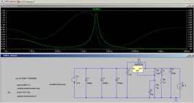
Interesting. In one case we can see a 7.5v resonant peak. How does that "sound" or manifests itself?
It's placed at about 35KHz, so there's no chance anyone will "hear" that, but I wonder how it does affect things, directly or indirectly.
My understanding is that the power supply will be less able to maintain proper regluation at the frequency of resonance. The lower the output impedance the harder it is for the load to modulate the supply. Thus if you have a resonant peak the load will be more likely to be able to cause the PS to modulate at that frequency, and I guess if it is bad enough it will oscillate.
Tony.
Tony.
I see. I just wonder, in cases where a transient current is needed by the load, will it draw it from this capacitor? Which is in general the reason power supply caps are there, I suppose. Or will it draw it directly from the LM317?good questions, and I can't give you a straight answer! I'd not thought about any capcitance on the load, and the potential effects of that. Perhaps when it is far enough away (assuming a few cm of wire between powersupply and the load) the problem is reduced.
The cap on the output is generally there to ensure stability of the regulator. The datasheet recommends using tantalum capacitors, these generally are not low esr. It is the use of low esr caps that makes addition of additional series resistance necessary.
a typical 1uF solid tantalum capacitor as specified in the datasheet probably has enough resistance to damp it to the point where it is not an issue. However if you were to use a 1uF film cap on the output it would be a very different story.
Yes the model does change with current. The resonant peak shifts when the current is varied (up to a point).
Tony.
Should it draw it from the cap, the peak wattage on the series resistor could be close to 2 watts if I see well. Not that it should introduce any problems, though. I feel the assumption about its proper wattage that we made above is still valid.
It would be quite enlightening to include a variable load in your simulations. I don't know if this is possible - little do I know about simulations yet. A variable current source would be a quite demanding load, and should give appropriate answers. Something like a 20kHz 0.6A rms value.
Again, not sure if anything like that is possible!
I've attached a zip file that should hopefully be a standalone directory with various LM317 circuits in it. You should be able to load any of them and run them without adding anything into your spice libraries (let me know if it complains that anything is missing).
There are a few different models that I have been playing with for doing different things. Hopefully they are of some use to people
The yarps powersupply I have actually built (I'm not 100% certain, but I think that is the final actual circuit). It was based on Fred's one transistor upgrade earlier in this thread, and the full gory details are available on my blog It was/is an excercise in overkill. My measurement gear is not really good enough for me to have formed a concrete oppinion as to whether or not it was a success, however from a point of view of it delivering +- 10V it was Sims have indicated using 6.6 ohms in one leg only, gives the same result as using 3.3ohms in both legs. if you feel uncomfortable with the resistors in the return line then feel free to ignore them
Tony.
There are a few different models that I have been playing with for doing different things. Hopefully they are of some use to people
The yarps powersupply I have actually built (I'm not 100% certain, but I think that is the final actual circuit). It was based on Fred's one transistor upgrade earlier in this thread, and the full gory details are available on my blog
It was/is an excercise in overkill. My measurement gear is not really good enough for me to have formed a concrete oppinion as to whether or not it was a success, however from a point of view of it delivering +- 10V it was Sims have indicated using 6.6 ohms in one leg only, gives the same result as using 3.3ohms in both legs. if you feel uncomfortable with the resistors in the return line then feel free to ignore them Tony.
Attachments
I see. I just wonder, in cases where a transient current is needed by the load, will it draw it from this capacitor? Which is in general the reason power supply caps are there, I suppose. Or will it draw it directly from the LM317?
Should it draw it from the cap, the peak wattage on the series resistor could be close to 2 watts if I see well. Not that it should introduce any problems, though. I feel the assumption about its proper wattage that we made above is still valid.
It would be quite enlightening to include a variable load in your simulations. I don't know if this is possible - little do I know about simulations yet. A variable current source would be a quite demanding load, and should give appropriate answers. Something like a 20kHz 0.6A rms value.
Again, not sure if anything like that is possible!
First a dsiclaimer
I'm just a guy with pretty rudimentary electronics knowledge who has read a LOT of datasheets, articles and threads on the LM317. has done LOTS of simulation, and quite a bit of real world testing of LM317 circuits. I don't have an EE background So with regards to your question. I don't think that there will be any significant current draw from the output capacitor, provided that the circuit is not transiently trying to draw more current than the LM317 and upstream components can deliver. The filter caps before the reg are providing this service more. The reason they are necessary is because of the pulsed nature of the rectification. The diodes only conduct for a brief period of time not continuously, and the capacitors tend to smooth this out, allowing current to be drawn from the cap at the times when the retifiers are not conducting. If you run the spice model for yarps and poke around looking at waveforms at various points such as straight after the bridge, then after the first cap etc you will see what is happening.
wth respect to the variable load, see the Voltage_vs_current model in the attached zip file
@Bonsai note that the LM317D (D for discrete) used in those circuits is only good to about 600mA, if you push it past that it will start to give you erronious results. It is the one I posted a bit earlier in the thread that I modified the transistors to get a more accurate voltage reference.
Tony.
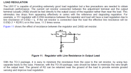
Yes, I can't remember which ones but some of the LM317 datasheets also show this. Along with the suggestion that the sense resistor (R1) above should be should be connected directly to the case of the regulator. The selection of the ground point for R2 also apparently makes quite a difference.
ok attachment is from the TI datasheet (it has a good explanation as to why), I think that the original Natsemi or possibly the Linear Technology one have a diagram almost identical to jackinnj's one. (actually I guess it was the LT one because jakinnj's one is an LT one )
I've read elsewhere, that this is probably the single most important thing for getting max performance out of an LM317.
Tony.
ok attachment is from the TI datasheet (it has a good explanation as to why), I think that the original Natsemi or possibly the Linear Technology one have a diagram almost identical to jackinnj's one. (actually I guess it was the LT one because jakinnj's one is an LT one
) I've read elsewhere, that this is probably the single most important thing for getting max performance out of an LM317.
Tony.
Attachments
Hello people,
what a really interesting thread, which I've been reading for about 2 hours now. As it exceeds my electronical and english language competencies I couldn't understand all of it. I'm happy to see people with a lot of knowledge participating their results with others. Unfortunatelly I've seen a lot of circuits during the last 20 pages and I cannot say, which is the best performning schemata. As the thread seems not to be carried forward anymore, please could somebody help me? I'm looking for a best performance regulated power supply for my amps bias and other works.
Many thanks,
Stammheim
The basic LM317 circuit does not have many alterations, really. If something is better is the use of a preregulator. Other than that, bypassing the adjust pin and using output caps for stability is all you can do, plus doing a proper layout design based on the above posts.
There are other regulators that - supposedly - perform better than LM317 regulators. You must specify the degree of quality, stability, noise, cost etc of your builds, to get further help.
There are other regulators that - supposedly - perform better than LM317 regulators. You must specify the degree of quality, stability, noise, cost etc of your builds, to get further help.
- Home
- Amplifiers
- Power Supplies
- Improving the LM3x7 regulator circuit