Thin film resistors run around 1000 Angstrom's in coating thickness. My back of envelope calculation says anything thinner than .005" should be okay for audio.
Ed.
Take 4 resistors of identical value.
Build a whetstone bridge configuration, and actually make it diamond shape exactly like the schematic.
Drive 1 to 10 Khz into the top and bottom nodes. Measure at the center right and center left node.
If the left-right ratios are perfect, there will be no center signal. If there is a mismatch (which there will be), you will get a small 1 to 10 Khz signal.
Now, take the wire feeding the top node current, and run it alongside the upper left resistor so it's current is close to that resistor to affect it via proximity. Take the wire feeding the botton node current, and run it alongside the lower right resistor for the same reason.
Now look at the center node difference. If there is a proximity effect, you will see harmonics. Harmonics cannot be caused by capacitance nor inductive coupling. Only proximity effects.
As a first guess, I would expect low ohm resistors to be more susceptible to proximity..but, that is a first pass guess.
jn
Last edited:
Any 12 ga resistors in your collection, SY?
Mine are measured in ohms.
if for a high quality product of any type, audio or not, you want it to machine well and last well. 6061 or 7075 grade (aircraft designations) are those alloys you want to use, as do I use them. they machine well, are more likely to be consistent from piece to piece or even across one large piece, as well as less prone to corrosion and stronger. aluminium corrodes too, but the lower grades need anodising to avoid it, 6061 and 7075 dont. (edit: they do eventually corrode, but its MUCH more resistant)
some will still anodise it, the cheaper grades may also have 'grain' which is picked up by the process and is all the way through the piece, it shows through the anodising too because it has slightly different electrical properties
John would be silly to not use it, there may be extra finishing processes that would add up to possibly cost the same anyway.
besides its sexy as hell!! =)
I would suggest 'hard' anodising using the 6061-T6. hard as nails. -RNM
Now look at the center node difference. If there is a proximity effect, you will see harmonics. Harmonics cannot be caused by capacitance nor inductive coupling. Only proximity effects.
do use nonmagnetic construction R for this experiment
but I would expect the AC bridge imbalance from proximity effect to be pure excitation frequency - no harmonics - exactly because proximity effect is caused by linear inductive interaction
I would suggest 'hard' anodising using the 6061-T6. hard as nails. -RNM
sure, my point is it is much tougher and more resistant to corrosion. for a product like this you would still anodise it, but afaik the 6061-T6 and particularly 7075-T6 are pretty resistant already.
What about R's used as potentiometers? Pot. contacts generate a bunch of measurable thd.... especially H3.
Easy to minimize- don't draw any significant current through the wiper.
When it comes to bulk aluminum, I only repeated what I was told by my deceased colleague, Bob Crump, a number of years ago…
Good Mr. Curl
“Aerospace grade” aluminium implies a lot of things (alloy composition is but one of them) but specifies nothing.
In aerospace industry it is mandatory for each and every material, component or assembly installed on an airworthy vehicle, to carry (or be able to be linked to) a “back to birth certificate”. This means all the signed, stamped and dated documents that prove conformance to production procedures and specs, together with the 100% (not sample) numerous inspections, storage and routing from day1.
If one is to use a metal alloy of some form for a non-aerospace application, he doesn’t need all that or he will have to pay an insane price.
The mere rigorously controlled specific heat treatment –or Temper- of an alloy (coded by a “T” followed by a number) alters the physical and mechanical properties tremendously.
Temper (select and read)
aluSelect: Tempers
Machining an already heat treated alloy?
")
if for
gusp, all well written. An 6061 T0 is in the ballpark.
George
PS1. At least with Ouzo there is a consensus here.
Much better than with aluminium or resistors.
Tell me what “grade” you are enjoying.
PS2. Some alloys in T0 state need to be stored in deep subzero freeze, or they will start to age-harden.
Last edited:
Does proximity effect depend on signal level, or is it like skin effect and only dependent on frequency? If the latter then no distortion.jcx said:but I would expect the AC bridge imbalance from proximity effect to be pure excitation frequency - no harmonics - exactly because proximity effect is caused by linear inductive interaction
To get distortion you need some effect which either depends on some power of voltage/current or on the absolute magnitude of voltage/current, and this effect needs to react back on the circuit operation. Heating can do it; it arises from the square of voltage/current and can react back via temperature coefficient of component values. Mechanical displacement (due to voltage or current) can do it in some circumstances.
do use nonmagnetic construction R for this experiment
Excellent advice.
Proximity effect by definition is the distortion of the current density profile as a result of the time rate of change of the magnetic field. Since distortion of the density profile results in less of the resistive material being involved in the circuit, the resistance will climb. Time varying resistance will create harmonics. Ed should see it with the AP if it is significant.but I would expect the AC bridge imbalance from proximity effect to be pure excitation frequency - no harmonics - exactly because proximity effect is caused by linear inductive interaction
Frequency and coupling. Impedance/resistance value may play a role.Does proximity effect depend on signal level, or is it like skin effect and only dependent on frequency? If the latter then no distortion.
jn
He DID NOT FORGET, he was trying to make it easy to see on an oscilloscope.
Actually, he used magnetic wire to enhance the skin effect for the measurement. But he forgot to include it in the calculation of the inductance of the wire.
Couple that with his lack of experience with low impedance measurements, the desire for a specific outcome, and a lack of peer review, and you end up with a publication of a poorly designed test methodology, bad results, and incorrect conclusions. Bad science..
JA also repeated the experiment, finding nothing.
jn
Too late ! You'll just have to figure out how you could live till now with all this hell in your amps !Before I get crazy with the scrutinizing of the feedback resistor (Rf) issue,
Thanks John, to have explained sincerely why you used your special plain aluminum case for your preamps. Cosmetic (weight and solid appearance) is important for the sells and image, respectable if it helps the sells and can change the reviewer's listening experience in a positive way
.In fact it is a very difficult to know what amount invested in this will give optimal results to the image, the benefits and the sells. Like the optimal price. Sometimes too much is too much, and not enough gives an impression of "cheap", even if inside is a wonder.
Last edited:
People can surely make a big deal about just about anything.
I presume that everybody knows that the Blowtorch chassis are relatively massive and are made by 'hogging out' a solid billet of aluminum.
Now there are different grades of aluminum, apparently, and one grade is called 'aircraft grade'. IF anyone would just 'wiki' "aircraft grade aluminum", it is there for all to see and understand, and REMOVE the speculation about it. If we as builders wanted to make chassis free of defects, and with a 'beautiful' surface finish, we would start with a 'good' billet of aluminum, and not something formed out of trash cans or something.
Of course it cost us more, but we got results and not rejects, as well.
When it comes to resistors, only confusion seems to be put forth. First of all, eddy current loss in resistors at anything below radio frequencies is pretty subtle, AND it does not generate harmonic distortion. The resistor leads and resistor traces are JUST TOO THIN to matter much in the audio realm, and bringing up what they worry about at CERN or some other place does not answer any questions here in this subject.
Now Ed Simon actually MEASURES resistor distortion and he has amazingly found a correlation between what we audiophiles prefer to use, and his measurements. It doesn't matter what others think, one way or another.
When it comes to potentiometers, it is another subject altogether.
Back in 1974, we found BIG PROBLEMS with first rate potentiometers in regards to HARMONIC AND IM DISTORTION. Some of the most expensive and best known potentiometers suffered from this problem.
Allen Bradley and Waters were the first pots that I measured that were AUDIBLY bad, and had to be dealt with. Now, it is known that LOADING THE WIPER is usually a bad thing to do, but many of you here do it all the time with one project or another, and nobody warns you off.
It is true that some pot fabrications are more tolerant to loading than others. For example, both Penny & Giles and Alps are pretty good, even when loaded somewhat, Bourns and Clarostat is OK too.
However Allen Bradley and Waters were bad, at least the ones made 30 years ago, and still marginal without significant loading of the wiper. It was easily measured with a ST analyzer, and probably still is today.
When it comes to ABSOLUTE SOUND QUALITY, even static distortion measurements do not appear to tell everything, so for my VERY BEST EFFORTS, like the earlier JC-80 or the CTC Blowtorch, we used either P&G or TKD pots. They are more expensive, but they work better too. Let's hope we can end this confusion and learn something new.
Comments in red..
cheers, john
edit: besides, there's only about 4 or 5 individuals here who would understand what CERN worries about, so I don't do that.
When it comes to resistors, only confusion seems to be put forth. First of all, eddy current loss in resistors (eddy current losses?? Did I miss something?? Who's talking about that?)at anything below radio frequencies is pretty subtle, AND it does not generate harmonic distortion. The resistor leads and resistor traces are JUST TOO THIN to matter much in the audio realm,(the leads yes. Serpentine SiO2 resistors, yes...bulk carbon, no. thin film cylinders, let Ed try the test) and bringing up what they worry about at CERN or some other place does not answer any questions here in this subject. (who said anything about what CERN worried about?? Don't divert there John..)
cheers, john
edit: besides, there's only about 4 or 5 individuals here who would understand what CERN worries about, so I don't do that.
Last edited:
OK guys.
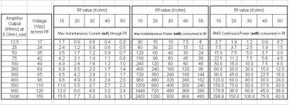
Before I get crazy with the scrutinizing of the feedback resistor (Rf) issue, I tabulated some calculations (attached ).
Plug your tempcos and the like and see what you will get from these.
I hope it helps
George
Looks like ur working on an advertizing campaign for bulk foil resistors
George,
100 W 6 ohms (?) P=E^2/R = Vrms=24.5 Vp-p = 69.29 at 10K =.48W Peak but really .06W. At 8 ohms Vrms=28.28 P=.08W So with a KOA/Speer 1/4W 10K Carbon film resistor I would expect .00052% distortion @100 Hz. from the feedback resistor. The LM4562 lists it's distortion as .0003% so the resistor is not as good as the "Horrible" opamp.
The other minor issue was the paper Dimitri posted was based on the research in the 60's when resistor distortion first really got attention. In those proceedings it was decided to be needed to test each resistor as they were not consistent. My method uses ten of the same and is used to select the manufacturer and type of resistor. They looked at third harmonic as it gave then the information they needed. The rest of the distortion they lumped into "Voltage Coefficient" With the much better gear today we can break out different orders of distortion, drift and increased noise.
Ed, any chance of trying the bridge? It would be interesting to see if you can detect any harmonics caused by proximity.bump
Also, perhaps you can try making my fancy schmancy zero inductance resistor on pcboard?
My design calcs are based on massive parallelism..
The .1 ohm I build recently uses 40 1 ohm resistors..20 in parallel, tied in series to 20 more in parallel. giving two .05 ohmers in series.
The layout give inductance of .375 to .4 nH max.. and eliminates external inductance. The actual inductance will be about but not above 8 nH divided by the number of resistors paralleled in one leg...this case 20. Higher partcount gives lower L.
jn
Last edited:
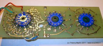
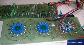
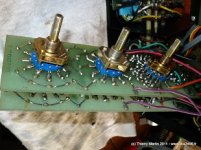
How we addressed this problem in 1970 ?Back in 1974, we found BIG PROBLEMS with first rate potentiometers in regards to HARMONIC AND IM DISTORTION. Some of the most expensive and best known potentiometers suffered from this problem..
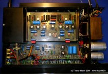
A 24 position array of resistances for volume, and 2x12 for Baxandall The resistor bridge was constant impedance source and they were a "physiological" filter following the Fletcher & Mudson curves.
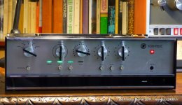
Scientelec Mach 50 was a 2X50 Watts rms combo, witch, more than 40 years later still measure 0.05% of THD @ 50 watts. It was sell 2000 Fr at this time. (2,551.69 today USD)
Attachments
Last edited:
- Status
- Not open for further replies.
- Home
- Member Areas
- The Lounge
- John Curl's Blowtorch preamplifier part II