Dimitri,
Third harmonic distortion is these days mostly from impurities in the resistance material or mechanical strain. Mechanical strain indicates a possible failure mechanism.
ES
Please read 4.1.3 of the reference, without DC bias TC creates third harmonic distortion. Thermodynamics, reversing the voltage does not make negative heat.
George,
The point was that the IC had less distortion than the feedback resistor. So the amplifier was was good enough or in other words not the limiting factor.
Scott,
Given 50 mW as the data sheet value (I don't know the production number) it would be a much higher number than the level at which I tested resistors.
As shown in the attached measurement of a higher wattage resistor at 50 mW, one could expect 12 db more distortion from the smaller resistor body, and another 9 to 12 from the low frequency content. (Most musical energy is found at the LF end say 150 Hz.) Then this is a sample of an Ohmite resistor, others of the same type of construction mostly measured worse and none better. So your distortion just from the feedback resistor could be -60 db. re full power. As there are thermal relaxation issues, the tail should be enough to be heard.
I suspect that is the actual limiting factor, not the rest of the circuitry. So to me this would be how to make a "Bright" or "Brings out ..." amplifier.
ES
Sigh..it's skin effect, not thermal..
")
jn
ps..just havin fun..Happy New Year Ed..
Last edited:
a separate Voltage coefficent of resistance is recognized by R manufacturers - thermal coefficient doesn't explain everything
skin effect shouldn't produce harmonics, IMD with linear conductive materials - it can be modeled as linear mutual inductances steering current to linear parallel R paths
skin effect shouldn't produce harmonics, IMD with linear conductive materials - it can be modeled as linear mutual inductances steering current to linear parallel R paths
Last edited:
Please read 4.1.3 of the reference, without DC bias TC creates third harmonic distortion. Thermodynamics, reversing the voltage does not make negative heat.
Wow Scott, you are right. Third is the dominant TC distortion for a dry resistor.
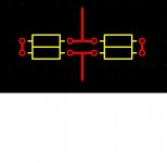
JN Should we talk about PC layouts that minimize inductance but allow for uniform heating? I like eight resistors, two on the top right, two on the bottom right, the other four same on the left. Resistors parallel to each other. Signal comes in splits to 4 goes through and then the other end is connected to the paired one and returns back the way it came.
Attached is a top view, same on the bottom but staggered so the pads don't touch.
ES
Attachments
Wow Scott, you are right. Third is the dominant TC distortion for a dry resistor.
ES
Avec Ouzo?

skin effect shouldn't produce harmonics, IMD with linear conductive materials - it can be modeled as linear mutual inductances steering current to linear parallel R paths
Why not??
Skin effect alters the volume of resistive material that carries current. At higher current slew rates, less material sees current so the resistance will climb. When the resistance is a function of the current slew, man, does that raise issues or what??
An important test to validate the current slew dependence of resistance would be to return the current next to the body of the resistor and compare it to a test where the current is far away. The return current will cause a proximity effect on the resistor current density profile.
jn
JN Should we talk about PC layouts that minimize inductance but allow for uniform heating? I like eight resistors, two on the top right, two on the bottom right, the other four same on the left. Resistors parallel to each other. Signal comes in splits to 4 goes through and then the other end is connected to the paired one and returns back the way it came.
Attached is a top view, same on the bottom but staggered so the pads don't touch.
ES
Don't forget, all the heat comes out of the leads for resistors. Standing them on end with a daughter board at the top of the resistors allows the interleaved pattern, as well as allowing the pc board artwork be used to conect half going up, half coming back. A trivial way to create my sub nano zero B dot resistors, and the best part is increasing the dissipation by design decreases the inductance, and the top board can also be heatsunk free air.
I'd recommend using this structure to create the feedback divider needed for most power amps.
The resistor design you're trying to make was created back in the late 80's if I remember correctly. It was a non inductive attempt for a TRR tester back in the day. I'll try to dig it up.
jn
where is voltage/current nonlinearity?When the resistance is a function of the current slew, man, does that raise issues or what??
Skin effect alters the volume of resistive material that carries current.
What's the thickness and resistivity of the films used in cheap carbon film or metal film resistors? How about expensive thick film resistors? Then as yourself, what frequency will it take to have skin effect be even vaguely in the ballpark for those devices? How does that compare with the effect of ordinary stray capacitance?
where is voltage/current nonlinearity?
When skin effect occurs, the current will be confined to less of the volume. As a result, the effective resistance will climb.
This is a typical problem for all conductors. At 60 hz, this effect will reduce a 6 inch diamater copper conductor to a 6 inch diameter tube with a wall thickness of 2 inches, leaving the inner 2 inch diameter core doing nothing. That is why the power companies do not use solid copper conductors thicker than 4 inches diameter for 60 hz distribution. The open inner part of the tube is also used to carry cooling water if high current density is required beyond air cooling.
With coils, this is called proximity effect. The net result is an increase in effective end to end resistance as frequency increases. Sullivan of Dartmouth has some good explanations on his site..
jn
good thing theres feedback hey...
i'm yet to see any measurement with a strange downward sloping gain vs FS due to resistors. i'm wondering at what frequency this effect actually has an effect? if any
surprisingly resistors in my experience have been fairly linear devices
i'm yet to see any measurement with a strange downward sloping gain vs FS due to resistors. i'm wondering at what frequency this effect actually has an effect? if any
surprisingly resistors in my experience have been fairly linear devices
Last edited:
What's the thickness and resistivity of the films used in cheap carbon film or metal film resistors? How about expensive thick film resistors? Then as yourself, what frequency will it take to have skin effect be even vaguely in the ballpark for those devices? How does that compare with the effect of ordinary stray capacitance?
Couldn't tell ya. I do know that back in the day, I had to watch out for carbon comps, as they'd skin and increase resistance as I went higher slew. For my 8 amps/nanosecond TRR fixture, I had to go with some BeO microwave resistors, they had a very thin resistive film over a beryllia tube.
I pointed out the effect and the proximity test to Ed so that he could quickly examine to what extent the current slew rate distribution would affect his measurements.
jn
Who said it wasn't?Why would 'skin effect' be important in resistors, and NOT in wires?
I just explained why it was to for 60 hz distibution, no??
With "wires" as you say, it will impact the end to end resistivity. It's important to consider the level of effect, however. For normal audio, we don't run the current density high enough for it to matter. A 12 guage wire at 20 Khz for example, has a current density at the center which is greater than 70% of the edge current density, so the actual increase in resistance is not measureable. (and I am very good at these measurements)
jn
Last edited:
it would not surprise me if it happened at some point, as the mechanism makes some sense (without deeper knowledge) but it seems unlikely it would effect an audio amp with the average audio resistor
I agree, it does seem unlikely..however, at -100 dB, who's to say? ...that's why I mentioned the test to Ed.
jn
- Status
- Not open for further replies.
- Home
- Member Areas
- The Lounge
- John Curl's Blowtorch preamplifier part II