I am big admirer of John Linsley Hood audio work and built some of his amplifiers. In other thread I needed simple but good output buffer and I remembered the one JLH used in his 80W MOSFET amp.
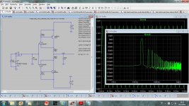
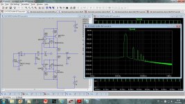
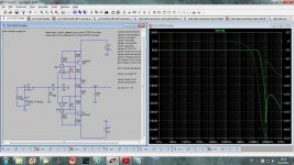
First is simulation of the JLH original buffer (with different BJT transistor as I do not have spice models for BC212/182). I am not sure how good are JFET models and here is just to show that buffer.
Next is simulation with better JFETs and result is quite pleasing.
dado
First is simulation of the JLH original buffer (with different BJT transistor as I do not have spice models for BC212/182). I am not sure how good are JFET models and here is just to show that buffer.
Next is simulation with better JFETs and result is quite pleasing.
dado
Attachments
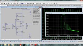
Next is simulation with better JFETs and result is quite pleasing.
dado
one more wire but with no voltage gain? ;-)
Finally this one work on with +-40 V.
I used this modified JLH buffer in a line amplifier in this thread http://www.diyaudio.com/forums/anal...conveyor-voltage-amplifier-7.html#post3273244
dado
I used this modified JLH buffer in a line amplifier in this thread http://www.diyaudio.com/forums/anal...conveyor-voltage-amplifier-7.html#post3273244
dado
Attachments
Any chance you can show a sim result of the simple sk170/sj74 borbely/curl buffer for comparison using the same spice models as above ? See f6 article for example
Could you show schematic?
Compensation
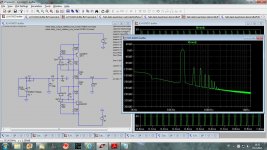
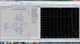
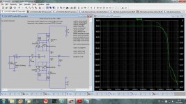
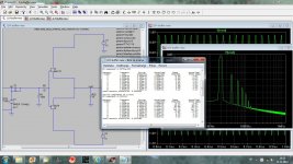
Cascoded JLH buffer will oscillate if not compensated properly. I did it with R3 and C7. Here are the Gains of compensated and non compensated Buffers. I tried different compensation and this one for me worked best. I would appreciate suggestions of different or better way to compensate.
Attached needed LTspice file if someone wants to experiment and I hope show result.
dado
Attachments
Could you show schematic?
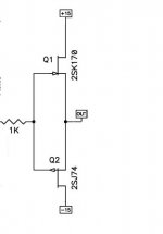
here is one ... (only ground connection not shown) - just interested to compare the sim results here to the ones you have got since i know the sound of this one quite well (ie doenst seem to have much 'sound' at all!)
thanks for sharing this interesting work
ps. this is from one of NP's schematics in case you were wondering ! supply voltage upto 25V no problems at all
Attachments
here is one ... (only ground connection not shown) - just interested to compare the sim results here to the ones you have got since i know the sound of this one quite well (ie doenst seem to have much 'sound' at all!)
thanks for sharing this interesting work
ps. this is from one of NP's schematics in case you were wondering ! supply voltage upto 25V no problems at all
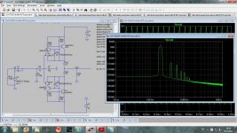
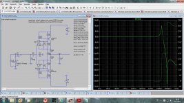
Here it is. It runs at Idss and in the case of my models it is 14 mA.
dado
Attachments
How about the DC-offset?
If you ask about last simulations it's -44 mV with the models i used.
Offset is easily cured by using a trimpot instead of emitter resistors or adjusting these resistors. Youll always have to as the transconductance of between the jfets is never the same.
Dadod something tells me youre running low jfet currents, I get much better distortion figures in Sims without using any cascodes. Ive been using this circuit since my teens to buffer long cable runs to amps. Its failsafe.
After a couple of years use I derived JLH super buffer, turn the cfp into a darlington by adding another transitor in each half and even using low gm parts youll surpuss the performance of the original. Low gm parts are actually mandatory to better control currents. With such a buffer even 100 ohm loads can be driven with practically unmeasureable THD. Interesting idea in the cascoding but I dont see much benefit in doing so.
Curl buffer doesnt even come close in the performance stakes.
Offset is easily cured by using a trimpot instead of emitter resistors or adjusting these resistors. Youll always have to as the transconductance of between the jfets is never the same.
Dadod something tells me youre running low jfet currents, I get much better distortion figures in Sims without using any cascodes. Ive been using this circuit since my teens to buffer long cable runs to amps. Its failsafe.
After a couple of years use I derived JLH super buffer, turn the cfp into a darlington by adding another transitor in each half and even using low gm parts youll surpuss the performance of the original. Low gm parts are actually mandatory to better control currents. With such a buffer even 100 ohm loads can be driven with practically unmeasureable THD. Interesting idea in the cascoding but I dont see much benefit in doing so.
Curl buffer doesnt even come close in the performance stakes.
The offset was for this circuit http://www.diyaudio.com/forums/soli...fer-homage-john-linsley-hood.html#post3279936 with no source resistors.
I know how to trim the offset.
I used cascode to have as low output influence to the input and to cancel Miller capacitance of the input jfet as I used cascoded buffer in my lineamp with current conveyor as it is very sensitive to that influence and distortion is to high without cascode.
I know that jfets are working better with current in upper part of the Idss and I am trying to do it in that manner.
dado
Maybe that influence is better controlled if you the cascode the cfp pair (not just the jfet)and refer the cascode voltage to the output ???. I ve used this sometimes instead although the improvement is not worthwile with such low THD already obtained. I prefer the super circuit for headphone amps as it can drive loads as low as youd like. Note you can have 100ma flowing in each half.
See the cfp as a single transistor, then add transistor to turn it into a darlington. I ll post the circuit a little later in the afternoon.
See the cfp as a single transistor, then add transistor to turn it into a darlington. I ll post the circuit a little later in the afternoon.
Here it is. It runs at Idss and in the case of my models it is 14 mA.
dado
Dado - thank you. Forgive me an obvious question - but what is the difference between the two sims you posted here ?
Also would it be too much trouble to post the sim and the models youre using so I can try it out also ? Thanks again
Dado - thank you. Forgive me an obvious question - but what is the difference between the two sims you posted here ?
Also would it be too much trouble to post the sim and the models youre using so I can try it out also ? Thanks again
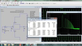
Input voltage, 1 Vpp and 5 Vpp.
See the cfp as a single transistor, then add transistor to turn it into a darlington. I ll post the circuit a little later in the afternoon.
Are you forgetting your promise again?
No, Im on a business trip and havent made it home yet. I apologize though, Ive drawn the scheme on a piece of paper and its not darlington but CFP. Just turn the BJT into a cfp, it couldnt be simpler. This wont help much in your case though as youre looking at low THD with high source impedance.
Last edited:
- Status
- This old topic is closed. If you want to reopen this topic, contact a moderator using the "Report Post" button.
- Home
- Amplifiers
- Solid State
- JLH Buffer - Homage to John Linsley Hood