this topology could be suited for the use in parallel mode to get very high output current (buffer for ribbon speakers);And here the cascode made with BJTs.
dado
additional this topology (pos. half) is a good basis for a Circlotron (CSPP mode).
The question for me is, what resistor value I need at least to avoid a Vbe multiplier section (emitter degeneration resistors R22/23).
This value determines the number of such stages for parallel mode for a given output current value
Last edited:
this topology could be suited for the use in parallel mode to get very high output current (buffer for ribbon speakers);
additional this topology (pos. half) is a good basis for a Circlotron (CSPP mode).
The question for me is, what resistor value I need at least to avoid a Vbe multiplier section (emitter degeneration resistors R22/23).
This value determines the number of such stages for parallel mode for a given output current value
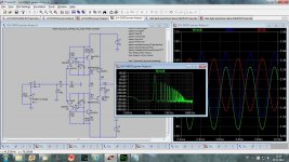
I did not try to simulate in that direction, and did not simulate thermal behaviour of this buffer.
Here is a try to get high current buffer, bias current is 1.8 A.
dado
Attachments
JLH Buffer
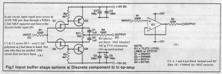
Just tried as best I can, to annotate a few scans of the circuits I used to build my JLH discrete buffer preamp. I hope they are useful.
Just tried as best I can, to annotate a few scans of the circuits I used to build my JLH discrete buffer preamp. I hope they are useful.
Attachments
JLLH Buffer preamp with JLLH Ripple Eater
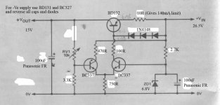
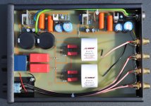
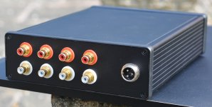
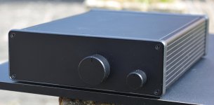
Just finished building a buffer preamp using John Linsley Hoods buffer stage powered by a simple linear regulator circuit and John's "Ripple Eater" circuit. Managed to get everything on one PCB small enough to fit in a rather smart Hammond instrument enclosure. Wired it all up using some sliver plated audio grade wire from Hi-Fi Collective and Mundorf Aluminium / Oil output capacitors and, driving some Pass A40 monoblocks, it sounds brilliant. Just thought I'd share a few photos.
Just finished building a buffer preamp using John Linsley Hoods buffer stage powered by a simple linear regulator circuit and John's "Ripple Eater" circuit. Managed to get everything on one PCB small enough to fit in a rather smart Hammond instrument enclosure. Wired it all up using some sliver plated audio grade wire from Hi-Fi Collective and Mundorf Aluminium / Oil output capacitors and, driving some Pass A40 monoblocks, it sounds brilliant. Just thought I'd share a few photos.
Attachments
Last edited:
Just finished building a buffer preamp using John Linsley Hoods buffer stage powered by a simple linear regulator circuit and John's "Ripple Eater" circuit. Managed to get everything on one PCB small enough to fit in a rather smart Hammond instrument enclosure. Wired it all up using some sliver plated audio grade wire from Hi-Fi Collective and Mundorf Aluminium / Oil output capacitors and, driving some Pass A40 monoblocks, it sounds brilliant. Just thought I'd share a few photos.
Very nice built. Did you use original JLH schematic? You could try with 2SK170, 2SJ74 jfets second schematic from my first post, much lower distortion.
I did not try to simulate in that direction, and did not simulate thermal behaviour of this buffer.
Here is a try to get high current buffer, bias current is 1.8 A.
dado
Q5 and Q6 (output transistors) have no thermal compenstation. It could only work in theory.
Q5 and Q6 (output transistors) have no thermal compenstation. It could only work in theory.
As I said I did not simulate thermal behavior, and I did not follow it further.
JLH Buffer Preamp
Circuit I built is virtually as original JLH schematic but the 1K pot is now replaced with two 470 ohm resistors. The output bipolars are replaced with MPSA06/56 and this reduces the quite audible hiss from the original BC184/214 to zero - result is a far more robust and transparent sound.
Very nice built. Did you use original JLH schematic? You could try with 2SK170, 2SJ74 jfets second schematic from my first post, much lower distortion.
Circuit I built is virtually as original JLH schematic but the 1K pot is now replaced with two 470 ohm resistors. The output bipolars are replaced with MPSA06/56 and this reduces the quite audible hiss from the original BC184/214 to zero - result is a far more robust and transparent sound.
Hi Earthloop, like your PCB layout, would you be prepared to share it?Circuit I built is virtually as original JLH schematic but the 1K pot is now replaced with two 470 ohm resistors. The output bipolars are replaced with MPSA06/56 and this reduces the quite audible hiss from the original BC184/214 to zero - result is a far more robust and transparent sound.
Many thanks,
James
Q5 and Q6 (output transistors) have no thermal compenstation. It could only work in theory.
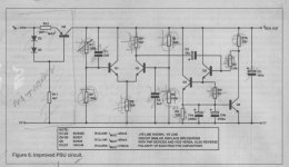
This is thermally compensated output buffer, D1 and D2 on the same heathsink with the output transistors. I hope it is not in theory now?
Attachments
This is thermally compensated output buffer, D1 and D2 on the same heathsink with the output transistors. I hope it is not in theory now?
It is until you try it in real life
")
Member
Joined 2009
Paid Member
It is until you try it in real life
Why are you so negative?
Not negative, just speaking from experience, spice it`s not so good in predicting thermal behavior. BTW, IMO cfp buffers sound nice but only in class A. Build it and then you`ll see how to configure bias tracking and offset (this might be good enough).
Thank you for your comments. Spice is good as models it uses.
This buffer uses CFP in driver only and it is Class A.
Thank you for your comments. Spice is good as models it uses.
This buffer uses CFP in driver only and it is Class A.
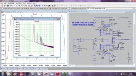
I`ve simulated the circuit with Cordell models and it does have very nice harmonic profile, but CFP driver goes out of class A when output stage goes out of class a ( for 4 Ohm load at higher output voltages), if you want the driver to stay in class A all the time you must disconnect it from the output node as in my schematic:
Attachments
I`ve simulated the circuit with Cordell models and it does have very nice harmonic profile, but CFP driver goes out of class A when output stage goes out of class a ( for 4 Ohm load at higher output voltages), if you want the driver to stay in class A all the time you must disconnect it from the output node as in my schematic:
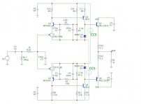
The other good way of keeping the drivers in class A all the time, ensuring high linearity, is loading each shoulder with CCS. However, in this particular case, it may be a little bit of overkill...
Attachments
I`ve simulated the circuit with Cordell models and it does have very nice harmonic profile, but CFP driver goes out of class A when output stage goes out of class a ( for 4 Ohm load at higher output voltages), if you want the driver to stay in class A all the time you must disconnect it from the output node as in my schematic:
Thanks Borko, I did simulate that way, and if I remember correctly I've got higher distortion, I'll try it again.
The other good way of keeping the drivers in class A all the time, ensuring high linearity, is loading each shoulder with CCS. However, in this particular case, it may be a little bit of overkill...
That too, thanks Valery.
- Status
- This old topic is closed. If you want to reopen this topic, contact a moderator using the "Report Post" button.
- Home
- Amplifiers
- Solid State
- JLH Buffer - Homage to John Linsley Hood