Thanks Borko, I did simulate that way, and if I remember correctly I've got higher distortion, I'll try it again.
Yes, a little higher distortion.
There are other ways to improve it but you`ll have more parts (complexity).
I`ve simulated the circuit with Cordell models and it does have very nice harmonic profile, but CFP driver goes out of class A when output stage goes out of class a ( for 4 Ohm load at higher output voltages), if you want the driver to stay in class A all the time you must disconnect it from the output node as in my schematic:
I simulated what you suggested, and with CCS as Valery suggested and in both cases distortion doubled. This buffer as it is stays in Class A at full power on 8 ohm and goes in class AB on 4 ohm load with not to much of distortion increase. It could be possible to force the drivers to stay in Class A on 4 ohm load with bias increase, but then BD139/140 are not powerful enough. I think that the buffer is good enough as it is.
Damir
Try to simulate this variant for distortion")
It does not help(normally that capacitor lowers crossover distortion and is of no use in Class A, but strangely it did not help here when working in Class AB for full power on 4 ohm load) distortion was even higher then without capacitor on 4 ohm load.
Borko thanks for help, if you like to play with it I can load .asc file, maybe you can make it better?
Damir
Yes it doubles second harmonic from 0.0005 to 0.001% at 1W, and harmonic structure stays as it is. I don`t think that`s the problem.
With the schematic distortion is reduced and the driver stays in class A all the time, give it a try.
Anyway, listening tests could say much more !
With the schematic distortion is reduced and the driver stays in class A all the time, give it a try.
Anyway, listening tests could say much more !
Member
Joined 2009
Paid Member
hello~
voltage gain possible with this circuitree? ^ ^
Look at the Nelson Pass F5 if you want this topology but with gain.
hi
It is possible using mosfet instead of Jfet in JLH buffer ?
It could be possible with depletion mode mosfets, but I don't know any complementary depletion mode mosfets.
and if we dont need complementary like a CIRCLOTRON ?
What CIRCLOTRON has in common with JLH buffer??
PCB Layout
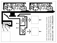
Here is PCB layout as png file created in "Free PCB" program. You could, perhaps, figure out component positions from my earlier posts. Don't have a diagram because it took me so long to figure out the layout that I sort of had the component positions embedded into my brain! Sorry for taking so long to reply!
Hi Earthloop, like your PCB layout, would you be prepared to share it?
Many thanks,
James
Here is PCB layout as png file created in "Free PCB" program. You could, perhaps, figure out component positions from my earlier posts. Don't have a diagram because it took me so long to figure out the layout that I sort of had the component positions embedded into my brain! Sorry for taking so long to reply!
Attachments
- Status
- This old topic is closed. If you want to reopen this topic, contact a moderator using the "Report Post" button.
- Home
- Amplifiers
- Solid State
- JLH Buffer - Homage to John Linsley Hood