I have a DE5 if you want to play with it. I was using it on my micro unities with the misco. It's tiny...MUCH smaller than the BMS 4540. Probably still pictures of it on Audio Psychosis.
DE5 you can get in the US either from US Speaker (special order not on site) or from Pro Sound Service. Both are having them drop shipped from B&C NA. 6 months ago the DE7 wasn't in the country.
DE5 you can get in the US either from US Speaker (special order not on site) or from Pro Sound Service. Both are having them drop shipped from B&C NA. 6 months ago the DE7 wasn't in the country.
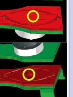
Here is my concept. I cheated and used a 3D modeling software.  The overall path length, 1/4 wave length, or what ever you wanna call it, is 6.75". The panels are 1/4" thick. The mouth opening is also 1/4" wide. I'm still working on it. I'm planning on adding some mids to it as well. With a little horn at the mouth I'm hoping to load this thing down to 200Hz. We'll see.
Front shot

Iso view

Bottom cross section

Side cross section

I hope I'm doing this right.
The overall path length, 1/4 wave length, or what ever you wanna call it, is 6.75". The panels are 1/4" thick. The mouth opening is also 1/4" wide. I'm still working on it. I'm planning on adding some mids to it as well. With a little horn at the mouth I'm hoping to load this thing down to 200Hz. We'll see. Front shot
Iso view
Bottom cross section
Side cross section
I hope I'm doing this right.
Your plan seems to be missing two important parts, the parabolic conical reflector at the throat entrance, and the 45 degree exit reflector.I hope I'm doing this right.
Attachments
Your plan seems to be missing two important parts, the parabolic conical reflector at the throat entrance, and the 45 degree exit reflector.
These things are so easy to build, I say just dive in and make one. No need to make this too complex.)
It gets a little trickier trying to get the path length math right when I've only got 10 fingers and 10 toes. I guess I can wing it and put something there. Would something be better than nothing?
So if you were doing one of these that had an equal radiation pattern, the slot and the internal reflector would both need to be round?
I would guess that maintaining an equal path length would dictate the shape.
No, the "eye" width determines the vertical dispersion, the horn side walls determine the horizontal dispersion.So if you were doing one of these that had an equal radiation pattern, the slot and the internal reflector would both need to be round?
An equal path length Paraline has only a few degrees of vertical dispersion at high frequencies, not a good feature for most single cabinet designs.
The Paraline allows for narrow vertical dispersion without the need of a long horn or coupler. To get the same vertical dispersion (only a few degrees at 16,000 Hz) my PA cabinets would have to be around 5 inches deeper using other coupler designs.
If I wanted "an equal radiation pattern", such as a 90 x 90 degree output, I would simply build a conical 90 x 90 horn, it would be the same depth as a Paraline designed for a 90 x 90 pattern.
Art Welter
Last edited:
Exactly Art, so if wanted equal dispersion, then both would need to change shape.
The paraline keeps the path lengths of the wave the same distance to the exit, right? The vertical exit of the eye at the slot is the same distance as the horizontal (round) part of the eye at the slot...keeping the wavefront intact.
Right?
So if I were doing something like the "Square-aline" that the OP has posted, then the eye shouldn't be eye shaped, but round to keep the wavefront intact and arriving at a single time at the exit.
This way (I think) you could load multiple drivers on a preexisting horn...providing you don't care about arraying the horns.
Just a thought from looking at the drawings in the patent...need to get a magnifying glass out so I can read the patent on the computer.
The object of the deflector in the initial throat area is direct the wave into the open guide and reduce or eliminate the reflection back into the throat of the device. The reflector at the end of the guide is directing the wavelength to pass out of the guide into the lens and not to just return through the path back to the driver also. /Think of these as directional control, where are you attempting to direct the waves. A simple or complex shape could be a simple as a round reflector or a parabolic reflector in the initial section and the same follows in the transition to the horn lens.
It gets a little trickier trying to get the path length math right when I've only got 10 fingers and 10 toes. I guess I can wing it and put something there. Would something be better than nothing?
Okay, we have a couple of things to address here:
#1 -
For anyone working on a Paraline, here's an easy way to size the mouth of the Paraline. The mouth width is (pi * internal height). For instance, with an internal height of 0.25", the mouth width is 0.785".
Here's the full formula:
mouth width = (2 * pi * radius * internal height) / mouth height
This formula is just 6th grade algebra. The Paraline is a disc-shaped horn that's been folded, and the formula for the surface area of a cylinder is 2 * pi * radius * height. (http://math.about.com/od/formulas/ss/surfaceareavol_3.htm)
^^ note that the mouth height is equal to twice the radius. So we can turn that formula into this:
mouth width = (2 * pi * radius * internal height ) / 2 * radius
which equals
mount width = pi * radius * internal height / radius
the radius variable in the numerator and denominator cancels each other, so we get :
mouth width = pi * internal height
which equals
mount width = pi * radius * internal height / radius
the radius variable in the numerator and denominator cancels each other, so we get :
mouth width = pi * internal height
Neat, huh?
Note that the mouth is subdivided in two by the reflector, so technically it's two long strips, each strip being 0.393" wide, and the reflector is in the center. The reflector will 'push' the mouth out a bit. If you're good with the CAD programs, you might want to account for that pathlength difference. But I'm way too sloppy to bother, particularly since it's at the mouth, where pathlength differences are a lot less important than at the throat. (At the throat of a horn a difference of even a fraction of an inch matters.)
#2 -
The cone-shaped insert near the compression driver is fairly critical. But in all seriousness, these things are really easy to build. My work is pretty sloppy, but if it were me, I'd just eyeball the piece and be done with it.
Home Depot sells some cone-shaped bits that are designed for furniture. The idea is that you hammer the piece into the bottom of your chairs so that they don't scuff up your hardwood floors.
Another option is to go to a crafts store. They have all types of odd shapes. (Jo Ann Crafts has this stuff.)
The reflector at the mouth is there to redirect the sound that exits the slot. Again, I'd just eyeball it. Go to Home Depot, buy a piece 1" x 1" x 96" piece of wood, then cut it at a 90 degree angle on your table saw or even with a hand saw. When you cut the piece of wood you'll end up with a piece of wood that's 1.414" at the base.
Last edited:
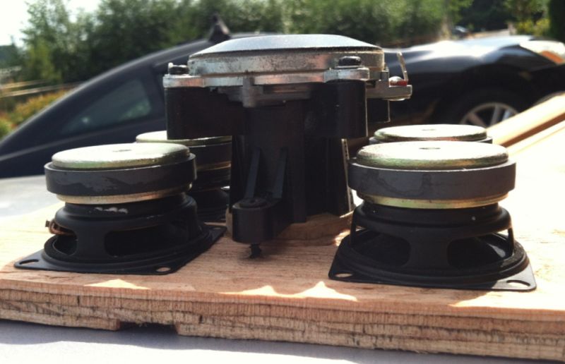
I like the idea of the woofer sitting over the top of the compression driver in a coax paraline. The BMS 4540ND is a natural choice due to its small size. It would be interesting to see what the newer B&C Speakers DE7 and DE5 compression drivers could do on a paraline. I have not found anyone selling them in the U.S. yet. Parts Express said they could custom order them. Before I get into that, I need to finish my current paraline project.
One of the things I've done to help visualize the driver layout for the paraline is print out true to size images of the drivers. This really helps determine if your driver placement will work in real life.
Selenium D2500Ti is a pretty nice small-format comp driver too.
Exactly Art, so if wanted equal dispersion, then both would need to change shape.
The paraline keeps the path lengths of the wave the same distance to the exit, right? The vertical exit of the eye at the slot is the same distance as the horizontal (round) part of the eye at the slot...keeping the wavefront intact.
Right?
So if I were doing something like the "Square-aline" that the OP has posted, then the eye shouldn't be eye shaped, but round to keep the wavefront intact and arriving at a single time at the exit.
This way (I think) you could load multiple drivers on a preexisting horn...providing you don't care about arraying the horns.
Just a thought from looking at the drawings in the patent...need to get a magnifying glass out so I can read the patent on the computer.
The inside of my Squaraline is square :
Paraline Folding - YouTube
Unity Paraline - YouTube
The upside of the Squaraline is that it's preposterously easy to build. No weird eye shape to compute, the inside is square.
It has a few downsides:
#1 - If you cut a piece of paper into a round shape and fold it over itself into a square (like in the first video) you'll see that there's a little bit of an overlap. I'd guess that in the overlapping portion you're going to get some comb filtering. Having said that, my measurement indicate that the Squaraline has output to 20khz, so it doesn't seem to perform any worse than a Paraline
#2 - As the Squaraline gets bigger and bigger, the mouth gets bigger. I have a suspicion that the high frequency output might suffer as the edges of the Squaraline mouth get further and further apart from each other. Ideally we'd want the edges of the mouth to be within about 1/3 wavelength. That's one nice thing about the Paraline is that no matter how large the Paraline is, the mouth width stays the same. (As the mouth width is simply pi multiplied by the internal height, so the mouth width will not grow larger no matter how large you make the Paraline. The mouth width is fixed.)
oh - forgot to mention -
Paraline Folding - YouTube
If it's not obvious from the folding scheme, the reflector at the mouth of the Squaraline should be a pyramid. And just like the Paraline, when you insert the reflector into the mouth of the Squaraline you should enlarge the mouth accordingly.
The formula for the mouth size of the squaraline is (pi * internal height * 2 * squaraline radius). And since the Squaraline is, well "square", then the width and heigh of the Squaraline mouth is equal to sqrt (pi * internal height * 2 * squaraline radius)
By far the easiest way to sketch out a Squaraline is to just cut it out of a piece of paper. For instance, if you want it to resonate at 700hz than it needs to have a radius of 12.14cm. (speed of sound / 700hz / 4) Just cut that out of paper, fold it by hand, then sketch that onto your piece of wood.
The throat, mouth, width, and depth could all be calculated, but I'm too lazy to write a spreadsheet for that just yet
Patrick, thanks for the math lesson. It'll take my a bit to absorb it all, but I'll update my CAD accordingly.
Of course! I'm figuring this out along with everyone else.
Here's an example of this:
Over on diyma (http://www.diymobileaudio.com/forum...-audio-discussion/135405-biggs^h^h-poppa.html) I've been posting the details on a new Paraline build. And we all know that Paralines are really shallow - about 1.25". One big problem I'm having with my new Paraline build is the depth of the drivers themselves.
For instance, the CDX1-1425 is about 2.5" deep. And that doesn't sound like a lot, but it's twice as deep as the Paraline itself! Plus, I had to include a spacer to get the midranges to fit.
To make a long story short, the depth of the Paraline plus the compression driver ends up taking up about 5" in depth. And that type of depth isn't a huge deal if the speaker is going in the house, but in the car, a speaker that's five inches deep makes a car nearly undrivable. (Especially when you're 6'3" tall like I am.)
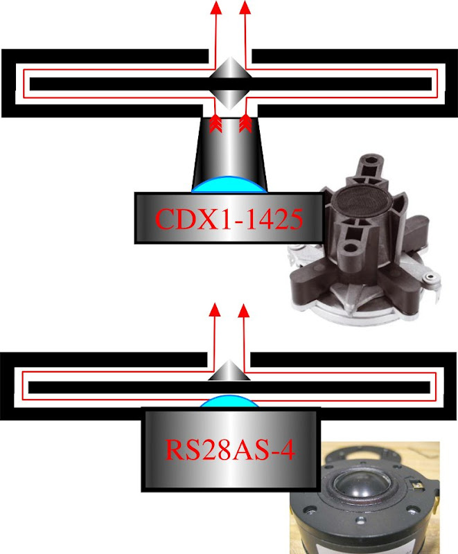
So here's my new idea. Swap out that compression driver and replace it with a dome. While dome tweeters are usually a terrible idea when you're making a horn, I think the Paraline is a bit of a special case. If you look at the pic that I've drawn above, I think you'll see that the path lengths of a dome tweeter aren't just good, they're arguably better than a compression driver.
For instance, in the top pic I've illustrated a Celestion CDX1-1425. I took mine apart, and measured all the dimensions. Basically the CDX1-1425 has a 1.4" aluminum dome that's focused into a 1" exit by the phase plug. Unlike most compression drivers, the dome isn't inverted. (I think this is mostly because the dome is so small - it's less than half the size of a B&C DE25. Because it's so small, Celestion gets away with a fairly crude phase plug.)
Anyways, the CDX1-1425 hits a 90 degree reflector at the throat of the Paraline. Now if we replace the compression driver with a dome tweeter, we can ditch the reflector. Basically the dome of the RS28 is touching the wall of the Paraline. I'd add a little bit of felt to keep it from buzzing.


Here's some pics of the RS28, courtesy of speakerdesign.net
Also, for fans of the BMS and B&C drivers, you might be interested to know that the Celestion CDX1-1425 and the Dayton RS28 have copper shorting rings. If I'm not mistaken, the B&C DE25, DE250, and the BMS compression drivers do not. The Celestion drivers are quite a buy.
The Dayton RS28AS is on clearance for $35 right now; I have four on the way and I'll post my results.
Last edited:
By far the easiest way to sketch out a Squaraline is to just cut it out of a piece of paper. For instance, if you want it to resonate at 700hz than it needs to have a radius of 12.14cm. (speed of sound / 700hz / 4) Just cut that out of paper, fold it by hand, then sketch that onto your piece of wood.
The throat, mouth, width, and depth could all be calculated, but I'm too lazy to write a spreadsheet for that just yet
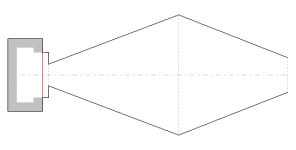
In theory, the sides of the mouth of a "Squaraline" should be curved to match the radius of the template, because the "fold" (slot) is square and thus the distance from the throat to the mouth will be greater at the corners than at the middle of the sides. But what really worries me is that a "Squaraline" has a pretty odd profile, similar to the attached schematic. I can't quite get my head around how it would work.
Attachments
If it's for treble only, the little $50 DE5 sounds really really good. Just lack the midrange power a 1" driver has.
If anyone wants one to play around with, I can loan you mine.
I would take you up on your offer, but I have to finish this first pair. If I had those things sitting around here I would be so distracted it wouldn't be funny. Probably almost like ADHD. I've got to stay focused while I actually have a little bit of time to work on this stuff.
- Home
- Loudspeakers
- Multi-Way
- Square Pegs