Terry Given,
Thank you for that information. I will study it carefully. I do know that at my home location this will be more than an idle study. I live directly below a 50kw FM radio station tower, within about 200 yards distance. There are also many microwave antenna and I assume some telephone and radio repeaters. I can here the station on my television, it blocks out cell reception by overpowering all cell brands that will lose the signal within seconds if you move a couple of inches and I have had problems with my McIntosh MA6100 picking up the signal. The only way that McIntosh could overcome this was to put some high pass filter somewhere in the circuit that definitely affected the high frequency output, it is noticeable to my ears. I can literally run a piece of zip cord to the sliding glass aluminum door frames and power a set of speakers like a fox hole radio I made as a kid. So if anyone needs to have proper RF filtering it is me. This is one reason I have been very hesitant to try and do any printed circuit layout as of yet. I want to know enough to understand the spacing of traces and the inductive pickup between parallel circuits. I understand the importance of ground loops coming from professional audio equipment all stringing so many devices together. I am certainly not afraid of power equipment as I have worked on the power side with some of my own manufacturing equipment and this included machinery that one piece used 85Kw at 480V and 3-phase power. Electrical power I can handle , but electronic circuit design is all together a different story. I am reading this thread very intently and am reading more than one book on design more than once to understand all the places that these problems crop up. I am living in an EMI/RF test chamber, if it doesn't happen here it probably won't happen anywhere else.

Thank you for that information. I will study it carefully. I do know that at my home location this will be more than an idle study. I live directly below a 50kw FM radio station tower, within about 200 yards distance. There are also many microwave antenna and I assume some telephone and radio repeaters. I can here the station on my television, it blocks out cell reception by overpowering all cell brands that will lose the signal within seconds if you move a couple of inches and I have had problems with my McIntosh MA6100 picking up the signal. The only way that McIntosh could overcome this was to put some high pass filter somewhere in the circuit that definitely affected the high frequency output, it is noticeable to my ears. I can literally run a piece of zip cord to the sliding glass aluminum door frames and power a set of speakers like a fox hole radio I made as a kid. So if anyone needs to have proper RF filtering it is me. This is one reason I have been very hesitant to try and do any printed circuit layout as of yet. I want to know enough to understand the spacing of traces and the inductive pickup between parallel circuits. I understand the importance of ground loops coming from professional audio equipment all stringing so many devices together. I am certainly not afraid of power equipment as I have worked on the power side with some of my own manufacturing equipment and this included machinery that one piece used 85Kw at 480V and 3-phase power. Electrical power I can handle , but electronic circuit design is all together a different story. I am reading this thread very intently and am reading more than one book on design more than once to understand all the places that these problems crop up. I am living in an EMI/RF test chamber, if it doesn't happen here it probably won't happen anywhere else.
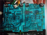
For example, the power amp I'm trying to fix has left and right speaker wires twisted together (where each pole of a channel made of a twisted pair, i.e. two wires of same polarity) and twisted with L and R input wires... this almost shocked me, since going from memory I would place L and R channels as far as possible (and the same between input and output)...
Stefano
twisting any differential pair together (eg + & - speaker wires) is a good thing. It reduces the loop inductance and adjacent loops face opposite directions so their magnetic fields tend to cancel out, making them much worse antennas. Its reciprocal too - externally imposed fields induce opposing currents in adjacent loops, which again tend to cancel out. Antennas are inherently reciprocal devices. an EMI engineers job is to make lousy antennas whereas an RF engineers job is to make good ones. all the same principles though.
So twisting the output leads together is good, as is twisting the input leads together.
It would be safe to say the output leads are a source of stray H fields (low output Z) whereas the input leads are good receptors (high Z), so twisting the outputs reduces the (internally emitted) stray H fields, and twisting the input leads reduces their ability to pick up stray H fields. IOW this reduces the source and stiffens up the receiver.
BUT.....and you knew there would be a but....
1. sticking the input and output leads in close proximity maximises what little magnetic coupling there is, so is a dumb idea - separation is almost always a good thing, but physical constraints mean it can only achieve so much, which is why twisting is so important. and after going to all that effort, bundling the twisted pairs together is just stupid.
2. twisting them together at the same time can negate any inductance-cancelling effects. if I have two twisted pairs with the exact same sized loops side-by-side, then the Rx loop is always in phase with the Tx loop (yeah this is highly unlikely in practice, which is why Cat5 cable works). But if I grab a bundle of wires and then twist them, I get the same effect - there is in effect no twisting between source and receiver. This is the worst way to do it!
3. thats just H fields. E fields are unaffected by twisting, they are capacitively coupled. sure dV/dt isnt going to be that high, but capacitance is inversely proportional to separation, so placing the input and output leads together maximises capacitive coupling, and is downright stupid.
So in conclusion: you are right to be shocked, that wiring harness is a good example of what not to do!
PS the really funny bit is the transformer wires are not twisted - and they carry the largest currents of all. Doh!
OnAudio #799 - feel free to try this; you will attempt to do so only once. regardless of how you choose to pick Zsec for termination, you'll end up dumping metric truckloads of power into your termination - anywhere from 100% to 2000% of rated VA.
an unused winding generates no H field - there is no loop within which current can flow. there is of course an E field, but its pretty well behaved with very low dV/dt = 2*pi*Fac*Vpk. this can be minimised by chopping the leads off, or just folding them back and forth a few times and securing with a cable tie (handy if you want to re-use the xfmr later).
Any other hairy mess (eg nastiness from ac line) that might be present on an unused winding will also appear on the other (presumably in use) windings.
Frank - yeah, fair enough. besides I think this will actually be harder for an audio amp than a smps - the smps generates truckloads of EMI so measuring emissions (easy) is enough to find the weak spots. but audio amps dont (or at least shouldnt), so you would have to do susceptibility tests, and then try and find the weak spots. this is much harder to do.
In practice almost all I ever do is:
1. do an emissions scan (OK this wont really help for Audio amps)
2. mercilessly dissect the gear, looking for any and all antennas (IOW bad layout/wiring/termination)
3. fix all the nasties I find - redo wiring harnesses, re-layout PCBs, correctly terminate
Often this suffices. if not, more drastic action is required e.g. I've seen a lot of SMPS that have little or no EMI filtering, but this is all an Audio amp would require.
KindHornMan @ #821 - ye gods, you are indeed the worst-case scenario.
every single untwisted pair will generate a ton of DM noise. twist everything, and use combined DM/CM filters. You might also want to put EMI gaskets on your enclosures - or at least fold edges over to provide a barrier to plane waves (the longest dimension of a slot is the critical one - so for the junction between a lid and an enclosure thats the length of the side (or between adjacent screws), rather than the gap between lid and enclosure. returns are a simple way of getting extra attenuation. A flat plate for a lid might as well not be there at moderately high frequencies.
Michel Mardiguians "controlling radiated emissions by design" is a great complement to Otts "Noise Reduction Techniques in Electronic Systems"
So in conclusion: you are right to be shocked, that wiring harness is a good example of what not to do!
PS the really funny bit is the transformer wires are not twisted - and they carry the largest currents of all. Doh!
Thanks a lot Terry for your kind feedback,
I added the shots of trafos and their wire just for that purpose. It seems the manufacturer decided to squeeze in a single box two separable power amps, with a less than smart PCB and wiring topology. Toroids wire seems too short to allow twisting. But the two power amps seems really sharing only the power switch and the fuse, so I'm thinking (fool?) of cutting the PCB in order to have one L unit and one R unit and rewire by separating input and output (the best would perhaps be input on one side, output on the other side?).
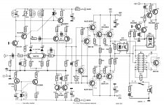
Trying not to to stay too much off-topic, actual PSU has 40000uF per channel, yet rails are really much longer than a couple of inches, so for sure there's a high inductive component opposing current demand of the Sanken output pair (and I don't like the "S" made by the rails in order to reach the second cap of each rail). Forgive my dumbness, is the addictive "local" capacitance to be added like on the attached schema, downloaded from http://www.audiofanatic.it/Schemi/Tipo/Stato_solido/finali/pic_finaliSS/200W_2SC2922_2SA1216.jpg?? The schema sports only two elcos C13 and C14, while - as per your findings - I would add a parallel of more elcos, a film cap and a snubber.
Thanks a lot and kind regards,
Stefano
P.S. and OT (sorry) about rewire: which variant of CAT5 speaker cable recipe are you satisfied with and would recommend?
Attachments
Looking forward, you did say tonight
"Tonight" might have been a WEE bit optimistic.
I haven't had much time to work on anything in the last few days. I did have a nice set of distortion vs reservoir capacitance plots and a table of the actual minimum C_reservoir for SQUARE-wave signals, with various transformer and load combinations, similar to the stuff I posted for sine signals, but decided I needed to re-run everything, before posting them, which will take a few more hours.
gootee,
So these numbers you are running of min. C against distortion are for a fixed transformer value. Is the transformer set for a minimum size or is this a large value transformer that would require smaller capacitor reserve?
Nobody answered my earlier question if we could have a chart of both a minimum sized transformer and large capacitor banks against a larger transformer with less capacitance and work between the two limits. Is this possible given a fixed distortion level or acceptable ripple numbers? We could then look at the power output requirements and select a combination between the limits that would satisfy the requirement.
A much broader range of amplifier power, presented as line graph capacitance per watts, would thoroughly answer my question if when the watts range is very broad.I will look into expanding the table I made, Daniel.
P.S.
I'm especially interested in "necessary capacitance for speaker frequency response, 3hz" with the 1 watt and other small scale power amplifiers, in comparison with larger amplifiers, to see if you get a shelf/flatline in the line graph throughout a range of miniature power amplifiers because of supporting 3hz to an 8 ohm load.
That gives me a somewhat related question. Can a CRC or similar method actually decrease the capacitance requirements that relate to getting excellent bass performance from a class AB amplifier?A ClassA amplifier that does not transition into ClassB and/or does not clip will only bounce back Audio frequencies on the the supply rails. That certainly gives the rectifiers and transformer an easier job. But there are still spikes coming in from the mains and they still give the PSU a real job to do.
Good evening(here)/day Tom,
not meant to enhance entropy, but do you think the local capacitance "effective" sizing is a function of output power (and or device Imax rating)? Finally I'm starting thinking that these capacitance is way more important than that one near the rectifiers and might end up being the larger one, although made of several paralleled units. If so, we might "save" on the caps nearer the rectifiers, just to have a voltage not too "jumpy" on the rails. Of course we have a similar reasoning for the VAS stage.
Nothing different from what you already showed, but I'd like to know if this "sounds" reasonable.
TIA,
Stefano
Stefano,
I follow somewhat what you are asking about the distributed capacitors in the chain. But could someone post a simple circuit drawing of the basic layout of how this distribution is done? Are you just physically moving some of the capacitors closer to the output devices along the power rail? That is what I am envisioning from the description of the multiple capacitors in the circuit. And CRC means capacitor resistor capacitor? A simple circuit would be nice to see also.
Steven
Hi Steven,
yes exactly, I was wondering if plainly move the capacitance where it's needed might be a simple solution to the issues given by parasitic inductance of the rails. I might be completely wrong but I understand the CRC as in Resistor-Capacitor (RC) Filters. In case of a power amp (like mine) with 2 caps/rail I was wondering if it might be the case to get rid one of one of them and move more capacitance (at least 1/2 capacitance for the +rail and 1/2 on the negative rail, with film bypass and a snubber) as close as possible to the output stage. This way we wouldn't have to add a R as the rails "offer" a resistive component "for free".
Hope it makes some sense,
Stefano
While already Dejan Veselinovic wrote in an old article on tnt to put the film caps and the snubber as near as possible to the output stages (Solid State Power Amplifier Supply Part 3), in this case we'd be moving much more than 100uF // 0.1uF // snubber network.
Stefano,
Thank you and also for the article on power supply. I have another question somebody can answer. The distributed small capacitors right before the output device are an electrolytic with a bypass film capacitor. Since these values are so small is there a reason that you do not just use film capacitors at this point. Why would you still need to use an electrolytic at this point? Is there something about the charging rate or discharge rate at this point that still demands an electrolytic cap? I keep wondering why something like a 10mfd 100v polypropylene cap would not work in this position?
Steven
gootee,
So these numbers you are running of min. C against distortion are for a fixed transformer value. Is the transformer set for a minimum size or is this a large value transformer that would require smaller capacitor reserve?
Nobody answered my earlier question if we could have a chart of both a minimum sized transformer and large capacitor banks against a larger transformer with less capacitance and work between the two limits. Is this possible given a fixed distortion level or acceptable ripple numbers? We could then look at the power output requirements and select a combination between the limits that would satisfy the requirement.
Kindhornman,
I think that what you are suggesting is possible, and sometimes actually necessary. It seems obvious that in some cases, we can trade VA against uF, such that with more VA we can get by with fewer uF before the charging-pulse shapes begin to bite into the output signal waveform
I posted a table of Cmin and plots of THD vs C, in this thread, for some simulated cases: 8 Ohms @ 100 Watts @ 25 Hz with 120 VA and 240 VA per secondary (i.e. per rail), and 150 W @ 4 Ohms @ 25 Hz for 240 VA and 360 VA secondaries, and 200 W @ 4 Ohms @ 25 Hz for 360 VA and maybe 240 VA (can't remember), in Post 740 at:
http://www.diyaudio.com/forums/solid-state/216409-power-supply-resevoir-size-74.html#post3134179
with a revision in Post 756 at:
http://www.diyaudio.com/forums/solid-state/216409-power-supply-resevoir-size-76.html#post3135425
(Note that I was only using THD as a means of trying to identify when the capacitance actually got too low and the power supply started to grossly deform the output waveform.)
The main problem I have is that I have only one transformer model that was actually constructed from physical measurememnts of a real transformer. And that one is for a simple 120 VA toroid, with primaries and secondaries paralleled to give that rating.
I've been using multiple instances of that one model to create a center-tapped transformer model, with various numbers of the 120 VA ones in parallel to model each secondary, like combining two transformers to create one center-tapped transformer. And I've had to raise the input voltage to try to model a transformer with a slightly-higher output voltage than the original's 25 VAC (i.e. 36 VCT).
I either need someone here (Terry Givens?) to tell me exactly how to change the model's parameters to scale it to different ratings, or, I need to physically measure and model some more transformers, or I need to get some other people to measure some transformers they have, OR, I need to find some good models on line.
The transformer-measuring steps are simple and few (but only apply to single-primary-single-secondary transformers, unfortunately) and all that is required is a variac, a multimeter, a low-value power resistor, and some connectors. The steps are given in the schematic for the spice transformer model, at:
Spice Component and Circuit Modeling and Simulation
Maybe not everyone has a variac.
Anyway, I think that I now also have a pretty-good method for calculating the % distortion and finding Cmin for square wave i/o signals in addition to sines (square waves being a harder test to pass than sines, if the same amplitude is used), in a fairly-automated sort of way.
So if I had a good way to handle the variation of the sizing of the AC input to the rectifiers, I could crank out some better data. (It would also be interesting to do something similar with regulated supplies.)
For our original purposes, here, I guess that just two or three commonly-used transformer voltages would be needed (unless we wanted to go up to higher-than-typical output power levels). But models for a range of VA ratings for each output voltage rating would be very nice to have.
Anyway, I should have some results, and the spice circuit and models that produced them, ready to post later this evening, for square waves.
Cheers,
Tom
Tom,
Now I have more to read.... Thank you for the explanations and telling the limitations that you give in your testing. And know I don't have a variac, I do have a variable power supply but I don't think that is really quite the same as a variac. I imagine that the variac has much more current capability than any variable power supply. I will have to look at the test setup that you are using, I do have some transformers that I could look at but I need to get them out of my storage but it isn't even close to home. I was looking at the cost of toroidal transformers and with the price of a new one you don't want to get the wrong one. The next question is should you use separate transformers for two amplifiers in a dual mono system or is it fine to split the power from one to drive both channels of a stereo amplifier? I imagine that the consensus is that two separate circuits would have some advantage in keeping each circuit separate, but what happens if you are using the same power circuit, at some point there would appear to be some inevitable interaction going on.
Steven
Dual mono and Monobloc is for a little bit more stereo separation at the cost of a lot more cash. But with only 1 transformer you can achieve some separation for a tiny fraction of the price by using Schottky series to V+ and V- to Each amplifier channel individually. In addition to the diode isolation, the small loss from the Schottky diodes creates an little bit of CRC type noise filtering. This inexpensive version of virtual dual mono from diyaudio.com member TheProf, is one of very few virtual dual mono schemes that doesn't alter/complicate your grounding scheme. Ordinary star ground does work best.The next question is should you use separate transformers for two amplifiers in a dual mono system or is it fine to split the power from one to drive both channels of a stereo amplifier? I imagine that the consensus is that two separate circuits would have some advantage in keeping each circuit separate, but what happens if you are using the same power circuit, at some point there would appear to be some inevitable interaction going on. Steven
Diodes can only block half the crosstalk noise--better than stereo config, inferior to dual mono config. The reason to use virtual dual mono instead of real dual mono is a matter of cost. The difference between dual mono versus stereo was small anyway, so the difference made by virtual dual mono (the middle ground) may be hard to detect--it might waste your time, but it is very inexpensive.
P.S.
Amplifiers that run the inputs from regs (private set of regs per right and per left) already contain virtual dual mono feature and those don't need dual mono expense.
Last edited:
- Status
- This old topic is closed. If you want to reopen this topic, contact a moderator using the "Report Post" button.
- Home
- Amplifiers
- Power Supplies
- Power Supply Resevoir Size