I concur. I have a watercooled PC that can put out close to 300 watts of heat at full tilt and 500 at 'burn' mode. It has just one small Swiftech pump and what we call '480'mm radiators (three 120mm fans on one and a single on the other). The waterblocks are designed to hinder flow and increase turbulence so the water has more time to absorb heat. I suspect a plain block of aluminum with less turbulence will fare worse.
I see temperatures of about 60 degrees on the GPUs and 52-55 on the CPU (these are internal diode measurements close to the hottest parts of the CPU). The water temperature goes up to about 48 degrees. The ambient in those days was about 40 degrees C (not yet peak summer in India), so not too shabby.
You also have the option of a heat pump between the FETs and the sink. I am planning on using a few of those to build a custom chiller for the hottest summer, and that can be switched off in cooler/humid seasons to prevent condensation.
When water flows through a gap, the water layer next to the solid surface is the laminar flow regime.
If the water speed is low, the laminar flow layer is thick. If the water speed is higher the laminar flow layer is thinner.
If the water speed is raised even further the laminar flow layer becomes very thin.
The laminar layer acts as an insulator, it reduces the amount of heat flowing from the solid surface to the turbulent layer.
The more turbulent flow one has in the fluid/water gap the more heat will be removed.
Vortices can be added to increase the turbulent flow and thus reduce the laminar flow thicknesses. Or simply speed up the flow for more turbulent flow. Either will remove more heat.
Slowing down the flow is NOT the way to improve the heat transfer!
Last edited:
Now I like That,got some good Ideas,from all of you!
I did make another steel tube if you will,I found some aluminum and will go after it soon,The 2 sided heatsinks works well,I used 2 square tubes one on each side of the fets,and clamped the 2 together squeezing the fets in between them,I have a pump and a 5gal. bucket no cooler/radiator yet,but I ran 2 amps or around 1.3 volts on the source resistors,and it was steady at 45 C at 24 volts on a stock F5,I turned down the voltage to 18v and it stayed at 41C ,I am going to go with .250" wall thickness on 2" square ALUM tubing,the .5" tubing that I connect the hoses to,will extend into the square tube and get some holes in the sides to spray the wall inside the square tube that has the fets mounted on the outside wall,squirt it in the back,lol.The fronts of the fets run hotter than the backs,surprised me ,I guess it's the plastic to metal,but I'm happy it does work, I'll get these 2 amps up and going then try the F5c,Thanks for the comments,at least I still have working FETS this time,The other ones had to be burried they smelled so bad...RIP,LOL.any more Ideas I'm all ears!!!!!!!!!!!!!!
Thanks,
NS
One question : if we try to remain within the specs of the JFET's would it be possible to build a Turbo by actually remain at 24V rail but going with two MOSFETS per rail ?
Regards, Stefan
Done that been there. What is the maximum voltagge you need from your amp
is the question you shuld ask yourself.
Me have 4 homs (nominal) speakers so vent to 26 V 2.6 A on twins
I have cascoded the J fets any way just to keep MR Miller at bay
And no stinky current limiters
I may build turbo 40 V rails just for kiks one day but as my room is prety small no much point in that altrought going balanced was planed from start.
Slowing down the flow is NOT the way to improve the heat transfer!
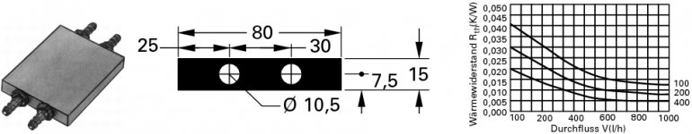
I have a standard solution to improve heat transfer.

Attachments

hi!
maybe a silly question, but is the standard F5 possible to drive a 3-way loudspeaker with an 8" woofer, an 5" for the middles and a ceramic tweeter?
I will DIY build this type of speaker:
Acoustic Design Wohlgemuth : CeraBlue
CeraBlue vom Markus | Lautsprecherbau
I tested my F5 on the bigger model with a 10" woofer, that was too much for it.
Maybe I can raise the 590mV to little more? (My DIY F5 is fan-equipped, so maybe no big temperature problems?)
regards,
Matthias
I tested my F5 on the bigger model with a 10" woofer, that was too much for it.
Can you describe what the mis-match or problem was?
why not .......
regarding bias - as long you're staying in 50W/device dissipation , well cooled .......
you can always put two pairs of output mosfets per channel , if lowish impedance of spks is a problem
or as a help to spread the heat
@6L6:
I tested the F5 and a 100W class AB amp (B&W I think, from a friend of mine) on the ADW Duetta speaker (10" woofer), and the bass was not as loud as on the AB-amp.
the sound on lower volumes was perfect- the typical NP sound
@Zen Mod:
The LS has got 8 Ohms, so that's not the big problem.
Your idea with the second pairs of Mosfets is veeeery good, I think I should try it. (If there is any place to put them onto the sink...
regards,
Matthias
...
CeraBlue vom Markus | Lautsprecherbau
I tested my F5 on the bigger model with a 10" woofer, that was too much for it.
...
What do you mean by "too much for it" ?
Your speaker didn't play loud enough or something else?
Is the impedance of that speaker lower than 2 Ohms ?
Now I like That,got some good Ideas,from all of you!
I did make another steel tube if you will,I found some aluminum and will go after it soon,The 2 sided heatsinks works well,I used 2 square tubes one on each side of the fets,and clamped the 2 together squeezing the fets in between them,I have a pump and a 5gal. bucket no cooler/radiator yet,but I ran 2 amps or around 1.3 volts on the source resistors,and it was steady at 45 C at 24 volts on a stock F5,I turned down the voltage to 18v and it stayed at 41C ,I am going to go with .250" wall thickness on 2" square ALUM tubing,the .5" tubing...
The Aluminum tube should help a lot, look up the thermal conductivity of steel and aluminum.... Being a lot larger and thicker is going to help a lot too..
Sounds like perusing around in the world of the extreme water cooled CPU overclockers for parts, or at least ideas would be time well spent.
I keep wanting to build some crazy watercooled and or weird/nonconventional heatsinked amp for the fun of it... but between procrastination, laziness, and lots of day job hours, I hang my head in empty handed shame....
Keep experimenting!!!
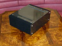
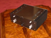
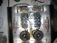
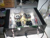
Just to let F5 fanciers know I haven't been sleeping I have just completed my 4th F5 amplifier. This time they are completely separate monoblocks in the same case. I used 300VA toroids from Tortech, fast rectifier diodes, Nippon Chemicon electros, Jim's F5 boards, silver plated RCA's and speaker terminals , separate speaker protection modules (Silicon Chip) with the stereo functions paralleled to carry lots of current . All the wiring from the PS rails and the amp outputs is done in Cat 6 wire. I simply stripped the pairs out and used a single pair (each wire in parallel) as connecting wire. I figured that as it made such great speaker wire I would use it for internal wiring as well. There is no doubt in my mind that these are the best sounding F5's I've built. An added bonus is that there is no audible hum in the speakers even though I'm not using a CRC supply.
Attachments
So everything is OK - you just can't expect the 25W amp to drive the speaker to same SPL as a 100W amp does.
Especially with only 15 dB of gain with the F-5....
Russellc
- Home
- Amplifiers
- Pass Labs
- F5 power amplifier