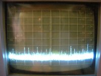
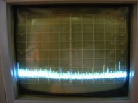
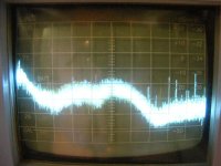
Here again are the measurements on power supply noise. With an ungrounded pair of diode bridges the power line noise only passes when the diodes conduct. Since they are on less than 30% of the time you get about a 5 db reduction in noise. Adding caps across the dual diode bridges improves things even more.
So John had an idea, tried it, found it worked and keeps on doing it. Sometimes the original idea is the correct mechanism and sometimes it isn't! But either way if it works, it works.
Shown is:
Dual Diode bridge W/O common Ground
Same with Diode Capacitors
RF noise from the transformer
Bandwidth is from around .1 to 5 MHz.
0 db is 1 mV
So the RF noise goes from 500 uV to 10 uV with four diodes and eight small capacitors.
Attachments
Last edited:
I think rectifying and smoothing each secondary separately and then connecting the ground of one to the V+ of the other to create a split supply is the most sensible way. This way, you absolutely keep he cap charging currents separate from the signal ground, making is easier to create a low noise supply. I also put snubbers cross each rectifier (c. 1nF and 470 Ohm resistor). A transformer screen takes care of noise that couples from pri to sec via the interwinding capacitance, although i found off the shelf PCB types dont have these- but if you order them custom, it pays to specify them Finally, a good filter on the main input side works wounds for RF conducted noise.
No magic here. These techniques have been used in instrumentation for at least 40 or 50 years.
No magic here. These techniques have been used in instrumentation for at least 40 or 50 years.
Last edited:
What happens when you DON'T use the transformer in a configuration that allows a center-tap?
You can use a battery. And indicator of it's charge, like bunch of LEDs of different colors, breathing calmly through narrow hole that acts as a gap antenna. .

John, it reminds me a soup opera indeed: all people who watch the movie know what happens next to the hero, but he still does not know.
Thanks Ed, that is just what we needed to satisfy certain critic's here, who do not have their own test equipment.
I have a scope. And when I short tip of the probe with it's ground crocodile near any wire that charges caps through diodes I see spikes.
How do you explain guys like Scott Wurcer, Bob Pease, Barrie Gilbert, Jim Williams, Bob Widlar, Bob Cordell, Nelson Pass, and on and on, who are far more successful and accomplished, yet are (or were) excellent explainers and never had to resort to insults and evasions when dealing with technical matters?
Because they have a degree of natural grace which is "old school". Consequently they would never consider the asking of such a question, let alone propose an answer. For many, today is too fast for such an attitude. "The King is dead, long live the King"(....too many contenders, too few born to the task.
They are, in history, known collectively, as "Pretenders". Those you mention, and to whom I WOULD add John Curl (+ a few 'subjectivists'; but certainly not on this thread), have deserved their crowns in their several fields. There are many paths to righteousness...not just those that the scientific illlumaniti define. We must never lose focus that the heightened experience of hearing is more important than the satisfaction of scientific requirement.OK, OK! Everybody learning about every permutation and combination of diodes and transformers to make a dual supply? There are others, why not show them?
What happens when you DON'T use the transformer in a configuration that allows a center-tap?
Attachments
We must never lose focus that the heightened experience of hearing is more important than the satisfaction of scientific requirement.
Yes, however we're talking about the operation of an electrical circuit here.
Yes, however we're talking about the operation of an electrical circuit here.
That is not the point which was quoted.....to 'part' quote can be evasive. That said, I realize that there is a gulf of difference between your - more scientifically knowledgeable - approach, and mine which - clearly - has no such background. I expect you can find Ezra Pound's lines to W.B.Yeates......
"Let there be commerce....."
I think rectifying and smoothing each secondary separately and then connecting the ground of one to the V+ of the other to create a split supply is the most sensible way. This way, you absolutely keep he cap charging currents separate from the signal ground, making is easier to create a low noise supply. I also put snubbers cross each rectifier (c. 1nF and 470 Ohm resistor). A transformer screen takes care of noise that couples from pri to sec via the interwinding capacitance, although i found off the shelf PCB types dont have these- but if you order them custom, it pays to specify them Finally, a good filter on the main input side works wounds for RF conducted noise.
No magic here. These techniques have been used in instrumentation for at least 40 or 50 years.
That is also how I see things, with the exception that I don't put snubbers across each rectifier, but small CLC's after them. Is there anything to say in favour of using the center tap as ground and saving 4 diodes?
vac
Here is one of the 'competition' preamps that beat me in the ranking. I had one for 10 years. It deserved its place in the ranking.
My problem is those who rank operate in their own universe, as I have said before I have been at TAS listening tests and the worst fears of the objectivists were realized. Nothing goes on that could be called a competition, it has been decades of performance art.
If a center tapped transformer is used to establish the center point of a dual polarity power supply, any imbalances, including AC ones, appear as current into the "ground". In a circuit with a single true star ground and no ground loops this is no problemo, but what real circuit has no ground loops?
Real circuits have two (at least) channels with their own signal grounds running off doing Lord knows what and having various other impure thoughts. Dirty current injected into an imperfect "ground" is only allowable without penalty with a ground loop free construction, a rare thing, usually requiring balancing or transformers. The dirty current injection is minimized by floating power sources up from ground until the last possible moment, then dropping 'em gently where they wanted to be all along. Isolation, then redemption.
Thanks,
Chris
To center tap or not to center tap, that is the question.
Moot for me. Single supply.
se

If a center tapped transformer is used to establish the center point of a dual polarity power supply, any imbalances, including AC ones, appear as current into the "ground".
In which ground, Chris? In my power supplies "ground" starts from where all outputs of all voltage regulators I use are connected in single fat point. It is the ground. What happens on wires before this ground is obvious, but it is not reflected on output of PS, nor on any other "ground" that is connected to this point.
- Status
- Not open for further replies.
- Home
- Member Areas
- The Lounge
- John Curl's Blowtorch preamplifier part II