Let's calculate. 250V on Zeners, 200V on 15K resistor. Current is 200/15k. Power dissipated on Zeners = 250 * 200/15 in miliwatts, that means about 3 Watt on all 3 Zeners. But total current is 13 mA. If your tubes draw 13 mA that means Zeners will not work.
I usually start from requirements, how much current should supply your power supply, then decide how to stabilize the voltage.
If say when tubes are cold all current flows through Zeners, it must not be higher that causes 5W dissipation on 100V Zener. That means no more than 50 mA. So, according to current consumption of yout tubes you may now calculate value of resistor, instead of 15K.
Oh..yes, you're right. Since there is 13mA channel and 150v/0.013= 11.5k. 11.5k of 0.013 = 1.94w. What if I could get some 200v zener, could it be better ?? But still I'm going to source and or design a simple regulator amount those 3 legs that I have and they're TIP50, MJE350 & IRF840. I'm aiming at something 30-40mA channel.
I did not post it. I even did not draw it on a napkin.
i know someone who draws on a napkin....

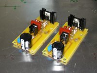
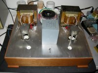
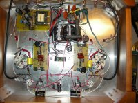
It's almost time to put everything together. Please comment if I could do better on lay-out and wiring.
I still have one question since the choke is only good for 230mA, but the tranny is good for 500mA. I'm thinking if I could re-route - RC after the rectifier - to make another supply for the 200v/& 250v supply ??
I still have one question since the choke is only good for 230mA, but the tranny is good for 500mA. I'm thinking if I could re-route - RC after the rectifier - to make another supply for the 200v/& 250v supply ??
Attachments

Hi there!
It has been a while since i last visited this thread, and it is very much related to my current project. Lots of great ideas! (ΓΥ-50 SE for guitar). So, I have around 480V HV, and a 3.5 KΩ transformer. So far, I have pushed the G2 up to 240Volts without issue. As Wavebourn says, I can almost go all the way up to HV+. (It is through sweries dropping resistor from HV+capacitor to ground) Could you please confirm?
And another thing that seems odd to me at least. Not one schematic here, from what i saw, includes grid stoppers. I thought it was standard practice?
Regards
And another thing that seems odd to me at least. Not one schematic here, from what i saw, includes grid stoppers. I thought it was standard practice?
Hi Costis,
well, compared to the most commom and usual AF power tubes, the GU50 features much lower gm, and thus perhaps isn't prone to oscillate?
Best regards!
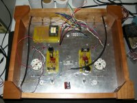
It seems taking too long for me to finish populating all the parts. I did have the filaments and HV checked. I didn't have gut to test it with tubes on, even after checking the schematic for couple times. Is there any way I could safely checking both channels step by step.
Attachments
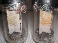
Look what I found in the Net. It reads, "P50 Experimental".
Later was renamed to Gu-50 when they started production.
Well, due to the fact that this tube was produced in the formerly GDR as P-50, this leads me to the assumption that it had found it's way to Russia via Eastern Germany. Am I right?
Best regards!
Well, due to the fact that this tube was produced in the formerly GDR as P-50, this leads me to the assumption that it had found it's way to Russia via Eastern Germany. Am I right?
Best regards!
Yes, and they had to pay a lot of License fees for the right to "copy the russian transmitting tube"...
at the former Telefunken Tube Factory in East Berlin where the LS50 was made - also known as "WF".
regards
Edit: this tube ist the SRS552M and SRS552N
Hi Costis,
well, compared to the most commom and usual AF power tubes, the GU50 features much lower gm, and thus perhaps isn't prone to oscillate?
Best regards!
I was referring not only to the power stag, but also in the pre/driver stages. No grid stoppers!
Hi there!
It has been a while since i last visited this thread, and it is very much related to my current project. Lots of great ideas! (ΓΥ-50 SE for guitar). So, I have around 480V HV, and a 3.5 KΩ transformer. So far, I have pushed the G2 up to 240Volts without issue. As Wavebourn says, I can almost go all the way up to HV+. (It is through sweries dropping resistor from HV+capacitor to ground) Could you please confirm?
No, don't worry. Just tie G2 and G3 to anode, that's it.
And another thing that seems odd to me at least. Not one schematic here, from what i saw, includes grid stoppers. I thought it was standard practice?
I did not try without them, use routinely.
Well, due to the fact that this tube was produced in the formerly GDR as P-50, this leads me to the assumption that it had found it's way to Russia via Eastern Germany. Am I right?
I heard that they were redesigned by Germans, frm LS-50 to Gu-50. But I am not sure they did that in Germany, may be in Sibera...
No, don't worry. Just tie G2 and G3 to anode, that's it.
I did not try without them, use routinely.
Sorry if I was not clear, I am referring to pentode operation. But I guess it's the same ratings.
I also use grid stoppers routinely. Thanks!
Sorry if I was not clear, I am referring to pentode operation. But I guess it's the same ratings.
I also use grid stoppers routinely. Thanks!
Ah no, for pentode operatin I would not recommend more than 300V on screen grids!
I personally use currents of screen grids as an idicator of clipping approaching, to control opto attenuator of input signal (second LED in series drives overload indicator).


Hi Wavebourn
Nice to see you around here.
Once I asked for the schematics of your Pyramid and you never answered.
Sure, for your buddies are available.
No matter, no longer need it.
Oops... Sorry, I never read all forum.


Hi Wavebourn
Thanks for sharing.
When you come to Argentina we eat an "asado"
It's like a barbecue but much more delicious.
Best regards
Popilin
You said that!
- Status
- This old topic is closed. If you want to reopen this topic, contact a moderator using the "Report Post" button.
- Home
- Amplifiers
- Tubes / Valves
- Help with these Russian GU50 tube amplifier