Hi:
I also upgraded the R//L Thiele with bigger 1.5uH inductors and 2 high quality japanese carbon composite 10 Ohm 2W resistors, using the "Corpius Method" too, soldered on a PCB board I got at Radio Shack.
Can you please post a photo of the other side of the thiele board you made?
Thanks
PEMO
Maybe the connection between the input ground and the star point was not good. If the input ground was still floating on that amp, you would have had nearly full rail voltage on the output. Had the protection circuit succeeded in protecting the LM, you would have fried the speakers. The fact that they are still alive makes it likely that the LM is fried indeed.Any other suggestions?
Did you check what happens when no speaker is connected? Use a dim-bulb tester aka light bulb tester to make sure that you don't destroy what is still working. Then make the measurements you would have done, if you had not been too impatient.
You should be able to test
- the supply voltages for correct value and polarity.
- the output for DC offset.
- the output function with a small test signal.
If the LM appears to be fried, you could unsolder the smoothing caps and measure continuity between power and output pins with the LM still on the board. That should be easier than unsoldering the LM.
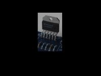
I was able to desolder the LM3886 last night, I used that "Chip Quik" product which is basically a solder made of alloy and a very clean flux. For those of you that don't know this product, it is simply great, I highly recommend it, you just apply a little bit of flux to each pin, then melt a little bit of the alloy solder on each pin, and this thing stays hot for few seconds, it melts the original solder allowing to remove the chip easily, no sweat at all. It would've been impossible to do it without it, I just have to order some more because I used all I had removing one LM3886.
Anyhow, I couldn't check anything on the PCB itself, and it actually got ruined because after I removed the LM3886 I tried to remove the caps using the conventional method with a vacuum pump and I lifted a couple of pads in the process.
I have the LM3886 intact, that's basically the only thing besides the input decoupling cap I could save. It is a shame that the rest of the components became garbage so soon... Well, I guess this is part of the game, sometimes one wins, sometimes one looses...
Since the shipping charges on these components were kind of steep, I ordered few items of each, so I just assembled another board with another LM3886, not the one I removed from the bad amp, proceeded to test it, and it worked perfect.
Now that I have both of the same amps working (I had one of the new ones in one channel and one of the old ones in the other) I can better compare the difference in the quality of sound. Well, these amps sound louder than the older ones, I think it is because of the input resistor or R4 in the PCB, the first time I used a 1K Ohm, and this time I used a 680 Ohm carbon composite, the 320 Ohm difference made a huge difference in the power, it now sounds much louder. The quality of the sound, well, it sounds louder and the treble seem to be cleaner, other than that I can't hear any other difference.
By the way, I forgot to mention that the PSU has also been replaced. I am using one based on the same XY PSU board, but with four Cornell Dubilier 18000UF 50V, Wima and Faratronics high frequency filter caps, a 1000V 50A rectifier bridge and two 4.7K Ohm 1/2 Watt metal film resistors.
Now, going back to the issue with the LM3886, is there any testing that can be done on these chips to determine functionality before soldering them to a board?.
Do they make sockets for these LM3886?. I'd like to be able to assemble a PCB just to test LM3886, being able to do so without soldering the chip to the board, is it possible?.
Do they make sockets for these LM3886?. I'd like to be able to assemble a PCB just to test LM3886, being able to do so without soldering the chip to the board, is it possible?.
Why not fit 1mm terminal pins and solder the 3886 legs to those ?
You can then desolder one pin at a time and move the leg to one side.
Pemo:
I'll try to post a picture tomorrow, but the connection is pretty straightforward, I used the components terminals to connect them with each other in parallel. Let's say that the inductors terminals are both connected to the connector blocks, then each resistor is connected to each inductor, side by side.
Redjr:
Thank you for your advice. I made a big mistake and was very lucky this time, I know the procedure, but since everything looked perfect to my eyes, and everything checked OK with the multimeter, and I'm a very impatient person, I decided to hook these things up to hear them. I won't do it again, the fact of the matter is that many of these components might be defective, so all precautions are to be taken. It is a good thing you posted the whole procedure in detail, thank you. By the way, did you finish your amp?.
Fabricated:
I will post the pictures with the speakers soon. Now with the new amps and the new power supply. How is your project going?.
As a matter of fact I did. I haven't put it into full-time service yet though. It sounds super clean, and I'm not getting the slightest bit of hum - that I can audibly hear anyway - even with my ear right up to the speaker cone. I had a little bit of re-work to do and changed out the input wires coming from the RCAs. I also changed my grounding scheme around a bit which helped with the hum issues I was having. Anyway, it's all good now and is working nicely with my new DAC and remote source selector I built. My next project is the Doug Self pre-amp that was featured in Elektor magazine a couple months back. I'll start another thread on that project once I get started.....
Redjr:
Thank you for your advice. I made a big mistake and was very lucky this time, I know the procedure, but since everything looked perfect to my eyes, and everything checked OK with the multimeter, and I'm a very impatient person, I decided to hook these things up to hear them. I won't do it again, the fact of the matter is that many of these components might be defective, so all precautions are to be taken. It is a good thing you posted the whole procedure in detail, thank you. By the way, did you finish your amp?.
Good luck on getting your amp issue(s) resolved. Sorry to hear about it. As cheap as those LM3886 modules are, it may pay to keep a couple around as backups. I have not used that chipamp yet, but I wonder if it could be socket-ed for easy replacement, or if that would just introduce to much noise? I know the pins are staggered, but you could use individual female header pins. Just a thot.
What about building up a "test module"? Using standard cheap but good commercial quality components
Build up a complete PCB except the 3886.
In those pads inserts sockets.
Slide a 3886 into those 11 sockets. Power up and test.
When passed, remove and solder into the real PCB.
The biggest difficulty is the odd pin pitch of the 3886 @ 0.067" (1.7mm)
0.1" sockets don't fit. Even omitting the unused sockets does not help.
I wonder of sockets removed from DIP packaged sockets could be spaced that close and still avoid shorting?
There's a job after my swim.
Last edited:
What about building up a "test module"? Using standard cheap but good commercial quality components
Build up a complete PCB except the 3886.
In those pads inserts sockets.
Slide a 3886 into those 11 sockets. Power up and test.
When passed, remove and solder into the real PCB.
The biggest difficulty is the odd pin pitch of the 3886 @ 0.067" (1.7mm)
0.1" sockets don't fit. Even omitting the unused sockets does not help.
I wonder of sockets removed from DIP packaged sockets could be spaced that close and still avoid shorting?
There's a job after my swim.
Andrew:
What kind of sockets? How do I search for them?.
Thank you.
not turned pin. They are intended for round PINs.
I have some 8pin DIP socket that accept blade type PINs.
Last night I pulled some of these connectors from a couple of DIP sockets. They look to be perfect for a test jig.
The only problem: the spare PCB I had was a from a damaged chipamp that did not protect itself due to my stupidity in breaking my own rule. You know the rule I'm talking about.
On trying to remove the damaged 3886 I damaged many of the pads. I hope I have enough time today to repair sufficiently to take a pic with my non macro camera to let you see the jig with and without a 3886 in place.
I have another question for you guys.
It has to do with this equation, you posted it here before:
Fc=1/(2πRiCi)
I tried to figure it out with these new amps I built, that in values, the only difference is in Ri (R4) in the PCB. New Ri is 680 Ohm, old Ri was 1K Ohm.
When I did it with the old amp value, I got this:
Fc=1/(6.28318x1000x47)
Fc=1/295309.46
Therefore, Fc=3.386Hz
Now, when I did this using the Ri value of 680 Ohm used in the new amps, I've got the following:
Fc=1/(6.28318x680x47)
Fc=1/200810.4328
so Fc=4.979Hz
Is this correct?.
Now the reason for the question. I've been listening to the new amps for a few days now, they sound good, but in my opinion the treble is too bright, the old ones sound better, more balanced, this is really hard to express in words but the sound of the old ones feel more harmonic. The new ones sound great too, but the high frequencies shine too much. Is that equation above the one to blame for that?.
Can you guys elaborate a little bit more on these low pass, high pass, -3dB concepts?. I've been reading on my own, but I can't get it. In this specific case, one amp has 3.386Hz and the other 4.979Hz, how does that translate into simple practical easy to understand terms?.
Pictures....!
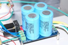
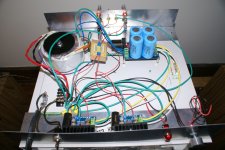
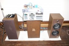
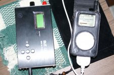
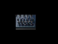
Here, some pictures including the new PSU with the four Cornell Dubilier 18000uF 50V caps, the new amps, the speakers and the two sources I'm using, iPod Mini and QLS QA350 WAV player. Also, the new Thiele R//L network with bigger inductors and resistors on a PCB board, as Corpius did it.
I know, I have to fix the wire mess, it looks terrible, but this is just for testing purposes. Now I have a very little hum if I get my ear really close to the tweeters, but with the first amps I had NO hum at all, that's why I haven't bothered fixing the mess. But I will eventually do. And yes, the left speaker has a stain on the front, but that's how I got them, I bought them used, but they sound great.
Pemo, I still have to take the picture of the back of the Thiele PCB, I didn't do it now because I have to disconnect it, I'll do it soon.
Attachments
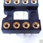
Here are pics of the test jig, using the sockets from a DIP8.
When the sockets are out of the plastic holder they are quite delicate and will not survive rough handling.
I have inserted and removed the 3886 from the jig a few times and it appears to work well.
When the sockets are out of the plastic holder they are quite delicate and will not survive rough handling.
I have inserted and removed the 3886 from the jig a few times and it appears to work well.
Attachments
Andrew:
Thank you. That is the perfect solution. How do I get those "sockets".
If I simply order a DIP8 socket, no more details, just that, will I get these things?.
Where did you get the PCB?. It looks like the one Pemo was talking about... I think I'll be getting the ones I ordered by tomorrow. I'll post pictures as soon as I get them.
Regarding removing the black border, I don't know, when I crop pictures I never get any border...
Did you check post 291?.
Thank you again for sharing your extensive knowledge and being so helpful.
DIP-8 Socket
Andrew:
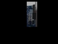
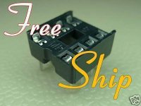
I found these two at the auction site.
They are different, one looks like yours, the other one looks sturdier, but I guess those pins are not coming out easily. Please check them out. Sometimes is a lot easier to find stuff at eBay because of the pictures...
Andrew:
I found these two at the auction site.
They are different, one looks like yours, the other one looks sturdier, but I guess those pins are not coming out easily. Please check them out. Sometimes is a lot easier to find stuff at eBay because of the pictures...
Attachments
How do I remove the black border where I have cropped the pic?
XnView Software - Free graphic and photo viewer, converter, organizer
The most effective FREE professional photo tool I have found. Excellent cropping and color/exposure adjustments.
BTW- GREAT solution to something I have been trying to figure out for a long time !!!!!
Last edited:
AndrewT/Pacificblue:
I removed the new amps and replaced them with the old amps yesterday. Now I have hum with them too. Very light, I have to get my ear very close to the tweeters to hear it, but it bothers me a lot since I didn't have it before. This is the main reason why I removed the new amps, the old ones never had any noise at all, but now they do, same as with the new ones.
If I remove the input cables from the source in the back of the chassis terminals, the hum goes away. But as soon as I connect the cable, the hum comes back. I already twisted some of the wires inside the amp, checked all the grounds, etc. The problem is in the inputs, but all the grounds are fine and connected, please help me, how can I troubleshoot this?. I believe that something happened the first time I switched these amps and that caused the hum that ended up affecting all the amps, new ones and old ones.
Thank you.
- Home
- Amplifiers
- Chip Amps
- Bought a XY LM3886 Kit.