Ok, things are getting a little confussing here...
My noise readings are 1.7mV AC and 1.6mV AC. I removed one of the input GRD cables, then made a cut in the one left in the chassis and connected it to both amps, the noise reading now is lower in one of the amps than the readings I posted in post #312 but the noise can still be heard, in the speakers and in the chassis.
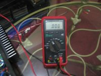
My multimeter is giving me those figures in the digital display, it reads 1.7mV AC and 1.6mV AC, it doesn't show any zeros.
I do not understand the post #317 either, "Mauro Penasa" boards and heatsink pictures...
My noise readings are 1.7mV AC and 1.6mV AC. I removed one of the input GRD cables, then made a cut in the one left in the chassis and connected it to both amps, the noise reading now is lower in one of the amps than the readings I posted in post #312 but the noise can still be heard, in the speakers and in the chassis.
My multimeter is giving me those figures in the digital display, it reads 1.7mV AC and 1.6mV AC, it doesn't show any zeros.
I do not understand the post #317 either, "Mauro Penasa" boards and heatsink pictures...
Last edited:
Lanchile:
Thank you for your advice. I already checked that cable in Parts-Express catalog, I am going to get some, it looks very good. Anyhow, I didn't have this problem before, that's why this noise is driving me crazy, I twisted all the wires in the chassis and instead on improving things are getting worse...
Thank you for your advice. I already checked that cable in Parts-Express catalog, I am going to get some, it looks very good. Anyhow, I didn't have this problem before, that's why this noise is driving me crazy, I twisted all the wires in the chassis and instead on improving things are getting worse...
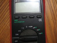
I am assuming it was an analogue meter?
What scale was it on, 1V? Or e.g. 10mV?
The specifications of the multi- or voltmeter will often tell you that the measurement has a certain possible error. If it had been a digital meter and you actually read 0.001V, the error in the measurement probably is big enough so that the actual voltage might be 0.00001V or 0.003V.
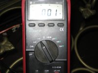
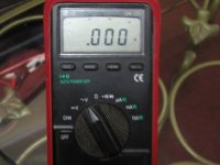
it is a digital one! As you can see here, it shows .001v and .000v
This is the amp kits http://www.hdamp.com/M400.html
Attachments
Last edited:
lanchile - That looks like a very interesting and simplistic amp. Only 4 output devices. Neat. I might have to look at that one for my next build. What kind of rail voltages does it require to get the spec'd 130wpc?
This M400 is one of the best amp kit I have ever build. to get the 130 watts RMS at 8 ohms you will need 60vdc per rail. This amp replaced my Bryston B60
I AM SORRY! I hacked this thread with my posts here. I will stop now!
Last edited:
it is a digital one! As you can see here, it shows .001v and .000v
This is the amp kits 2sk1058 2sk2221 irfp9240 mosfet amplifier schematic
Try to push the "RANGE" button a few times, it might give you a range more appropriate for measuring mV.
EDIT: Nevermind... According to the specs here, it should have a 320mV DC range, but indeed only a 3.2V AC range. It's simply not suitable for this measurement.
As said, the 0.001 has no meaning. It's somewhat like trying to measure inches with a rod that only has a scale in feet.
I get confused by accuracies of meters all the time at work, so I won't try to teach a course on it here
But as seen in the specs I linked, the basic 1 year VAC accuracy of said meter is 1.2%. I'm assuming this is 1.2% of the scale.
So if the meter is 1 year old, it can already be off by 1.2%. The scale is 3.2V so the measurement could be off by 1.2% of 3.2V which is 32mV. So trying to measure 1mV with a meter that can already be off by 32mV, is understandably, not very useful.
I'm not even touching the base accuracy which can make this worst case scenario even much worse.
Ignorance is bliss. I remember the time when I didn't know anything about significant digits, accuracies, tolerances, etc. It was a happy time.
Tekko, mine is "dead silent" too if I remove the input signal cables...
The trick is to have it "dead silent" with all connections in place, power, input and output, have you tried that?.
Did you cut the bridges in the input signal GND on the PCB board?.
Mine used to be "dead silent" when I first put it together with all cables connected, I don't know what happened when I removed them from the chassis just to try the new ones I built, then I started hearing the hum in the chassis and by the speakers. I have tried many things but none seem to work, my next step is to remove everything from the chassis to relocate the transformer, power supply and amps, hopefully this will take care of this hum problem.
Yours, you have to try with ALL connections in place... Please let me know if you did cut the input signal GND bridges in the back of the PCB or not.
Lanchile, more details....! Please!
Lanchile, this is an open thread, there is no hacking here... Just post...
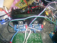
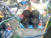
Now, out of curiosity I checked your amp too, I'm not sure but it looks like one of those amps designs by Nelson Pass... Can you please provide more details about them?. How many of those M400 boards are needed to build a stereo amp, one or two?. Can they be powered by an unregulated power supply similar to the one we are using here to power the LM3886 boards?. How are you powering yours?. Can you post pictures?.
This M400 is one of the best amp kit I have ever build. to get the 130 watts RMS at 8 ohms you will need 60vdc per rail. This amp replaced my Bryston B60
I AM SORRY! I hacked this thread with my posts here. I will stop now!
Lanchile, this is an open thread, there is no hacking here... Just post...
Now, out of curiosity I checked your amp too, I'm not sure but it looks like one of those amps designs by Nelson Pass... Can you please provide more details about them?. How many of those M400 boards are needed to build a stereo amp, one or two?. Can they be powered by an unregulated power supply similar to the one we are using here to power the LM3886 boards?. How are you powering yours?. Can you post pictures?.
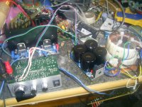
I found hum in mine was caused by wires running past the transformer.
Moving them reduced the hum quite a bit although there is a still a small amount still there.
That's what I'm going to do next, I'm going to relocate everything so there is no wires running on top of each other. Anyhow, this is funny, when I first put these things together, ALL my wires were a total mess but there was NO hum of any kind. When I removed the old amps to try the new, I twisted some wires to make it look neat, that's when the hum started....
POST COPIED FROM ANOTHER THREAD, BY ANDREWT.
****This a a post from AndrewT I found at another thread about the same LM3886 PCB's. I am posting it here because it includes information about calculating the Ci Ri to obtain the correct frequency response of these amplifiers, which at the end will determine the quality of sound they will produce, perhaps the most important aspect to calculate when choosing components****
Hi,
keep the 1r0 in the output feed.
Add a 1uH air core inductor in parallel to the 1r0. This converts the output from a Zobel load to a Thiele Network for amplifier output.
The Thiele Network helps avoid instabilities in the amplifier better than a Zobel alone.
The 22uF 500V and 10k for the input filter is a bad recommendation.
Try using between 470nF and 4u7F plastic film cap at the input as your DC blocking capacitor.
I like the bass sound that comes from using 1uF and 91k giving an F(-3dB)=1.7Hz. This is roughly equivalent to the specification of -1dB @4Hz that is fairly common in good retail offerings.
You can mimic the same high pass rolloff with any RC combination that has a 91ms RC time constant.
However I believe this works only when this input filter determines the bass response of the amplifier. This demands that the NFB cap be sized to match the input cap.
NFB cap >= sqrt(2) * Cin * Rin / Rfb.
Many use the NFB cap to roll off the bass rather than at the input and I think this gives poor bass sound. It's fairly easy to add parallel caps in these two locations if you start with both being too small and find what combinations suits you, your speakers and your room.
Using the values in post6
NFB cap >= 1.4 * 22uF * 22k+1k / 680r >=1050uF ( a silly number for this amplifier.) Any smaller than 560uF and the NFB cap becomes the passband filter (= bad in my opinion).
Change Cin to 2u2F and the NFB cap becomes >=105uF. Use 120uF or 150uF or 220uF (not 22uF).
__________________
****This is the equation I found in one of National Semiconductor Datasheets: Fc=1/(2πRiCi)****
Lanchile, this is an open thread, there is no hacking here... Just post...
Now, out of curiosity I checked your amp too, I'm not sure but it looks like one of those amps designs by Nelson Pass... Can you please provide more details about them?. How many of those M400 boards are needed to build a stereo amp, one or two?. Can they be powered by an unregulated power supply similar to the one we are using here to power the LM3886 boards?. How are you powering yours?. Can you post pictures?.
Gracias Aguilabrava! Well, The minimum power is 30vdc and the maximum is 60vdc. you can use unregulated power supply with no problems. These kits are mono, so you will need 2 boards for stereo. I have build many of these amps for my family, they are the best so far. and I did build some from Aussie amplifiers too, but these M400 are way better than NXV200. all what is said from their web is true. These are killer amps!!!! They sound so good that I sold my BRYSTON B60 integrated amplifier, my M400 replaced the Bryston.
Last edited:
One other point about the interaction of wires and induction.... When you do have to cross wires try to cross them at 90 degrees. That will help with hum issues too.That's what I'm going to do next, I'm going to relocate everything so there is no wires running on top of each other. Anyhow, this is funny, when I first put these things together, ALL my wires were a total mess but there was NO hum of any kind. When I removed the old amps to try the new, I twisted some wires to make it look neat, that's when the hum started....
Excellent points! Dining room in-wall light dimmers too. For those finding that's the only available place in the house for projects.May or may not apply - but also look for noise makers in the area. Fluorescent and Halogen lamps with rheostats are infamous for driving amp builders nuts.
Tekko, mine is "dead silent" too if I remove the input signal cables...
The trick is to have it "dead silent" with all connections in place, power, input and output, have you tried that?.
Did you cut the bridges in the input signal GND on the PCB board?.
Mine used to be "dead silent" when I first put it together with all cables connected, I don't know what happened when I removed them from the chassis just to try the new ones I built, then I started hearing the hum in the chassis and by the speakers. I have tried many things but none seem to work, my next step is to remove everything from the chassis to relocate the transformer, power supply and amps, hopefully this will take care of this hum problem.
Yours, you have to try with ALL connections in place... Please let me know if you did cut the input signal GND bridges in the back of the PCB or not.
I meant dead silent with everything connected and the source transitioning between songs or beeing paused. I have not done any cuts what so ever, i just soldered the components on and hooked it all up.
A video: LM3886 - YouTube
Tekko:
That is great!!! That's the way mine used to be. According to the experts here, you were supposed to cut the bridges in the bottom of the PCB, the negative pad for C4, to separate the input GND from power GND to avoid GND loops. These GND's then join together in the star GND outside of the PCB's. But if you have no noise, then I guess you are good.
That is great!!! That's the way mine used to be. According to the experts here, you were supposed to cut the bridges in the bottom of the PCB, the negative pad for C4, to separate the input GND from power GND to avoid GND loops. These GND's then join together in the star GND outside of the PCB's. But if you have no noise, then I guess you are good.
AndrewT or Pacificblue
Andrew or Pacific:
I'm trying to get the 220uF capacitors to use as feedback capacitor or Ci, instead of the 47uF I've been using. I want to try these in the new PCB's found by Pemo, the problem is that these 220uF caps in the 50V range are too big to fit in the board. Is it OK to use a 220uF cap of lower voltage?. The 35V ones of the same capacity are smaller, I was wondering if these can be used instead of the 50V ones, since this will filter the input signal only. Is that correct?.
My second question is regarding the input AC coupling capacitor. I used a 4.7uF 400V MKP type before in the XY PCB's, but the location on these new boards make it impossible to use those. Can I use a smaller cap in this location, something like a 1.5uF 100V MKP type?. Will that have any impact on the quality of sound?. I think not since it is just a coupling capacitor, there is nothing in the datasheet that indicates otherwise but I want to make sure I'm in the right path.
Gracias Aguilabrava! Well, The minimum power is 30vdc and the maximum is 60vdc. you can use unregulated power supply with no problems. These kits are mono, so you will need 2 boards for stereo. I have build many of these amps for my family, they are the best so far. and I did build some from Aussie amplifiers too, but these M400 are way better than NXV200. all what is said from their web is true. These are killer amps!!!! They sound so good that I sold my BRYSTON B60 integrated amplifier, my M400 replaced the Bryston.
Lanchile, can you post pictures of your amp?. Specially the inside...?
- Home
- Amplifiers
- Chip Amps
- Bought a XY LM3886 Kit.