The NFB cap sees < a few mVdc or mVac when working properly. It does not need a rating in excess of the supply rail voltage.
If rge amp goes faulty and sends near supply rail to the output then the inverse parallel diodes across the NFB cap limit the fault voltage to <=70mVdc.
Use a 10V or 16V or 25V or 35V or 50V or 63V cap in this location. Choose by size and cost and sound quality, not voltage.
The input cap should never have more than a few mVac across it, but can have a few tens of Vdc across it. Use a 35V or 50V or 63V or 100V film cap here. Again choose by size and cost and sound quality, but this time do include voltage.
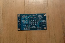
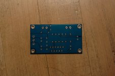
PICTURES: The new "Pemo" LM3886 PCB's.
Hi:
Here, the pictures of the "Pemo found" PCB boards for the LM3886.
After checking them out, I see that the Input Signal GND is connected to the Power GND as it is the case in the XY LM3886 PCB's. The bridges to cut are in the negative pad for C8, please correct me if I'm wrong.
I also would like to know if there is a need to add the RF filter capacitor in parallel to the resistor located in the + input signal to GND, as we did in the past with the XY PCB's.
Thank you.
Attachments
Hi Andrew:
Thank you once again.
I already ordered few Panasonic HFQ series caps in the 220uF 50V range because these will fit in the PCB, they are 10mm in diameter by 21mm in lenght. I was reading that this HFQ series was replaced by the FC which I have seen some good reviews about, my only concern is age, these were last manufactured by year 2000, hopefully they will be good.
For the AC coupling MKP type I'm looking for one around 1.5uF in the 150V range, there is only about 8mm pitch in the PCB for this cap and its location makes it impossible to use the cylindrical type used in the XY boards, this has to be one of those "Wima shaped" caps, and it is becoming hard to find one that has less than 15mm pitch in the legs. Do you have any suggestions here?.
My typing was crap.The NFB cap sees < a few mVdc or mVac when working properly. It does not need a voltage rating in excess of the supply rail voltage.
If the amp goes faulty and sends near supply rail to the output then the inverse parallel diodes across the NFB cap limit the fault voltage to <=700mVdc.
Use a 10V, or 16V, or 25V, or 35V, or 50V, or 63V cap in this location. Choose by size and cost and sound quality, not voltage.
The input cap should never have more than a few mVac across it, but can have a few tens of Vdc across it. Use a 35V or 50V or 63V or 100V film cap here. Again choose by size and cost and sound quality, but this time do include voltage.
here is the corrected post
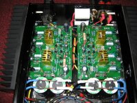
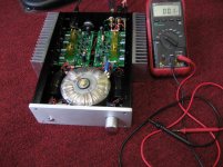
Lanchile, can you post pictures of your amp?. Specially the inside...?
This is the inside.
Attachments
Lanchile, thank you!
It looks great!
They show 2 amplifier kits, yours, the M400 which they say produces 130W at 8 Ohm, and the T300, which produces 150W at 8 Ohm. Why did you decide to get the M400 instead of the T300 that produces 20W more?. Is the M400 better sonically than the T300?.
It looks great!
They show 2 amplifier kits, yours, the M400 which they say produces 130W at 8 Ohm, and the T300, which produces 150W at 8 Ohm. Why did you decide to get the M400 instead of the T300 that produces 20W more?. Is the M400 better sonically than the T300?.
At Aguila. I have made 7 of the new boards and one complete amp with the XY boards.
The latest one is with better caps. I used nichicon muse capacitors as well as wima MKP polypropylene 0.1 mfd capacitors. You are correct only the polyester ones come in that dimension. So what I have done in bend the leads at right angles and mounted two from above and one from below. I have also used panasonic 2.2 mfd polypropylenes for input caps.
Just wanted to ask you one question though. Did you find any improvement in isolating the signal ground from power ground. What I have done for the XY amp is that I have kept the ground floating. Secondly I have taken 1 mm thick multistrand wire and connected the two power grounds of the PCB board. From the midpoint of this connecting wire I have attached another copper wire to the XY power supply board. The amp is dead silent.
Had picked this solution from some forum and it really works. No hum without the mess od star grounding. I will be posting the new PCB schematic that I have made. The new ones that you have posted are the actual implementation of the 3886 as published by National semiconductor and are copies of the chip amp.com.
Last edited:
Lanchile, thank you!
It looks great!
They show 2 amplifier kits, yours, the M400 which they say produces 130W at 8 Ohm, and the T300, which produces 150W at 8 Ohm. Why did you decide to get the M400 instead of the T300 that produces 20W more?. Is the M400 better sonically than the T300?.
I build the T300 for my friend too. Both sound really good, but I like the M400 better. I have ordered 10 M400 kits so far. Beside the M400 has fewer parts as you can see. and I do not need the extra 20 watts. right now my power supply is 42vdc per rail so I am not even using all his power, since to get the 130 watts you will need a power supply of 60vdc per rail.
That amp looks like a discrete design to me and not a LM3886 based one.
it is a discrete amp! I posted it here because Aguilabrava asked me to post picture.
At Aguila. I have made 7 of the new boards and one complete amp with the XY boards.
The latest one is with better caps. I used nichicon muse capacitors as well as wima MKP polypropylene 0.1 mfd capacitors. You are correct only the polyester ones come in that dimension. So what I have done in bend the leads at right angles and mounted two from above and one from below. I have also used panasonic 2.2 mfd polypropylenes for input caps.
Just wanted to ask you one question though. Did you find any improvement in isolating the signal ground from power ground. What I have done for the XY amp is that I have kept the ground floating. Secondly I have taken 1 mm thick multistrand wire and connected the two power grounds of the PCB board. From the midpoint of this connecting wire I have attached another copper wire to the XY power supply board. The amp is dead silent.
Had picked this solution from some forum and it really works. No hum without the mess od star grounding. I will be posting the new PCB schematic that I have made. The new ones that you have posted are the actual implementation of the 3886 as published by National semiconductor and are copies of the chip amp.com.
Thank you. Can you please post the part numbers for the Panasonic 2.2uF capacitors, and if you can, include the Wima part number too. I've seen some Panasonic polypropylene caps at Mouser with a 15mm pitch, I'd like to check yours...
Regarding improvements in the separation of the Input Signal GND from Power GND, I can't really elaborate on this topic since ALL the XY's I have done have the GND's separated, but you and Tekko haven't done it, and you both claim to have totally noise free amplifiers... I'm curious now...
This would be a question for AndrewT and Pacificblue, they are the ones that suggest doing it, not only on this thread where it is illustrated with pictures and described in great detail, but in many other threads in this website. Perhaps, I should build one without cutting anything to compare with the separated ones...
That amp looks like a discrete design to me and not a LM3886 based one.
You are right, I asked him to post those pictures and more details about his amp, I am interested in getting one of those in the near future. I figured that maybe some other people here might be interested in learning more about them too.
I build the T300 for my friend too. Both sound really good, but I like the M400 better. I have ordered 10 M400 kits so far. Beside the M400 has fewer parts as you can see. and I do not need the extra 20 watts. right now my power supply is 42vdc per rail so I am not even using all his power, since to get the 130 watts you will need a power supply of 60vdc per rail.
Lanchile, what would be the ideal transformer to get the full 130W per channel?.
Lanchile, what would be the ideal transformer to get the full 130W per channel?.
The M400 to get 130 watts RMS you will need a 60vdc per rail
Lanchile:
Would this one be ok?:
http://www.antekinc.com/pdf/AS-4222.pdf
It is a 22Vac, dual secondaries, 400VA, that I think would produce 62.21Vdc after rectification, is this right?.
Or you mean using a 42Vac, dual secondaries, 400VA, that would give 118.77Vdc after rectifiication, like the one below:
http://www.antekinc.com/pdf/AN-4442.pdf
I get confussed by "per rail", does this mean 60Vdc aprox. when measuring from +V to GND and -V to GND, or by measuring from +V to -V?.
The one I'm actually using for the LM3886 is a 28Vac dual, after rectification I get about 80Vdc if I measure from +V to -V, or about 40Vdc if I measure from +V to GND and -V to GND. If this is what "per rail" means, then I guess the correct one would be the 42Vac dual, that will produce a total of 118.77 from +V to -V and 59.38Vdc when measured from +V to GND and -V to GND...
Can you tell me where the right answer is?.
Lanchile:
Would this one be ok?:
http://www.antekinc.com/pdf/AS-4222.pdf
It is a 22Vac, dual secondaries, 400VA, that I think would produce 62.21Vdc after rectification, is this right?.
Or you mean using a 42Vac, dual secondaries, 400VA, that would give 118.77Vdc after rectifiication, like the one below:
http://www.antekinc.com/pdf/AN-4442.pdf
I get confussed by "per rail", does this mean 60Vdc aprox. when measuring from +V to GND and -V to GND, or by measuring from +V to -V?.
The one I'm actually using for the LM3886 is a 28Vac dual, after rectification I get about 80Vdc if I measure from +V to -V, or about 40Vdc if I measure from +V to GND and -V to GND. If this is what "per rail" means, then I guess the correct one would be the 42Vac dual, that will produce a total of 118.77 from +V to -V and 59.38Vdc when measured from +V to GND and -V to GND...
Can you tell me where the right answer is?.
The second one will be very close! I believe it will be around (42x1.4) 58.8vdc after rectifier and caps. The first one is for those gainclones ones (LM3875)
Last edited:
These are the panasonic capacitors
ECWF2225JA - PANASONIC - CAPACITOR, 250V, 2.2UF, 5% | element14 India
These are the wima, used two over the board and one below to make them fit.
http://www.wima.com/EN/mkp10.htm
100pcs WIMA MKP10 0.1uF 250V Audio Polypropylene Capacitors | eBay
Here is the schematic of the PCB clone that you posted: I have made 2 XY ones and 7 "nemo" as you call them ones two of which are with upgraded components, nichicon muse, panasonic and wima MKPs. Will compare the latter to my ultimate BOM MyRef Rev E lated. Waiting fot the enclosure.
http://chipamp.com/docs/lm3886-manual.pdf
Hope this helps.
Last edited:
- Home
- Amplifiers
- Chip Amps
- Bought a XY LM3886 Kit.