The same as those for a bypassed lower cathode, as the LED has roughly the same AC effect as a bypassed resistor.
Thanks a lot, very useful information.
Best regards
Johann
That's your proposed schematic?
No, not mine.
I was just offering to fix it for you.
To me all this stuff is crap.
Pick a Mu-follower.
No, not mine.
I was just offering to fix it for you.
To me all this stuff is crap.
Pick a Mu-follower.
I see this Mu-follower link: The Valve Wizard -Mu Follower
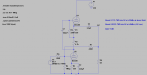
Gain 60
Output impedance 267R
An externally hosted image should be here but it was not working when we last tested it.
Last edited:
You're both right.
This is a Mu-follower circuit, from which you can tap off
a standard gain-stage at the anode, or
a signal off the top of the high cathode for "Mu-stage" behaviour.
The stage topology stays the same, but the interstage hook-up
changes the quality of the output and its 'Mu-havior'. ( <-- Just coined by Nazaroo!)
In simplified terms:
= this:

---------------------------------------------
On the other hand, this,....
equals this:

Is everything clear?
= this:
---------------------------------------------
On the other hand, this,....
An externally hosted image should be here but it was not working when we last tested it.
equals this:
Is everything clear?
You're both right.
This is a Mu-follower circuit, from which you can tap off
a standard gain-stage at the anode, or
a signal off the top of the high cathode for "Mu-stage" behaviour.
The stage topology stays the same, but the interstage hook-up
changes the quality of the output and its 'Mu-havior'. ( <-- Just coined by Nazaroo!)
Coin it -- Define it
Have you added something new to the thinking?
I disagree. As I said, whether it is an active load stage or a mu-follower depends on where you take the output. Take it from the lower anode and there is no follower action, so it is not a mu-follower.nazaroo said:You're both right.
Member
Joined 2009
Paid Member
Last edited:
I have just checked Morgan Jones. He is ambiguous on this. When he first introduces the circuit he says that output can be taken from either place, but later he says that the output impedance is low (which is only true for the cathode output). I may be the only one marching in step, but I think my definition is correct.
Here The Valve Wizard -Mu Follower says yes.
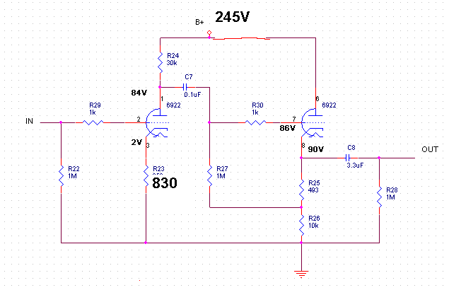
I used that circuit for my 6CA7 PP amp. Taking the output from the lower triode to drive a cathodyne inverter. Sounds excellent.
Attachments
I used that circuit for my 6CA7 PP amp. Taking the output from the lower triode to drive a cathodyne inverter. Sounds excellent.
Yes: Here's what stays the same, and may arguably be the most important points:
(1) The PSRR remains awesome.
(2) The signal is hardly affected by the altered loading, if you're smart, and reproduction of original program material remains accurate.
The Mu-stage may not be being used as intended, but it remains a great audio stage.

You guys are splitting fine red hairs (we need a photo). That circuit (mu-Follower) was used in low noise radio receivers and wide band pulse amplifiers in the Manhattan Project long before it was coined the mu-Follower.
There is plate output where the output is taken between the plate resistor and the plate. There is cathode output is taken between the cathode and the cathode resistor. Along came a tube CCS in place of the plate resistor. Throw in a couple of resistors or not between the top triode and the bottom voltage amplifier (remember that the top tube has a plate resistance think of it as just another resistor between the tubes). Now that there are two tubes in series is it plate output or is it cathode output, or some degree of tween depending on where the output is placed.
Explain Mu-behavior as the circuit existed before the name?
DT
That circuit, or the cascode? A mu-follower might not work too well in a wideband amplifier as it maximises the effects of both anode stray capacitance and Miller capacitance.DualTriode said:That circuit (mu-Follower) was used in low noise radio receivers and wide band pulse amplifiers in the Manhattan Project long before it was coined the mu-Follower.
I want use 3 stages:
1st stage. Using ECC82/12AU7 wich topology is better for line input low noise?
-Cascode
-SRPP
2nd stage. Using ECC82/12AU7 wich topology is better for high gain line stage?
-Cascode
-SRPP
3rd stage. Using ECC88/6DJ8/6922 line cathode follower.
All suggestions will welcome.
1st stage. Using ECC82/12AU7 wich topology is better for line input low noise?
-Cascode
-SRPP
2nd stage. Using ECC82/12AU7 wich topology is better for high gain line stage?
-Cascode
-SRPP
3rd stage. Using ECC88/6DJ8/6922 line cathode follower.
All suggestions will welcome.
- Status
- This old topic is closed. If you want to reopen this topic, contact a moderator using the "Report Post" button.
- Home
- Amplifiers
- Tubes / Valves
- 6DJ8/ECC88-SRPP Tube Preamplifier