Let's try the textbook way of figuring what tubes to use.
Start from the output stage:
- We figure a pair of 6L6's with plate voltage of +300V into your OPTs with 3k6 primaries will bias up at about -17V. So the driver stage needs to put out a push-pull signal of 20V peak (to be safe), on the plus and minus sides.
- In an LTP-phase splitter, the gain is halved (it sees only a single-ended input to one of its inputs, the other is grounded).
The 12AT7 has a mu of about 50 (when plate loaded), so can reach a gain of maybe 25 in the LTP. That means that if we had 1V pk available at the input, a single 12AT7 LTP could drive your 6L6 output stage to full power. (Since a CD player can put out over 2.5V peak, it's safe to say there's even a margin for 6dB of NFB with a 12AT7 LTP.) The first tube socket could then be used for a pentode CCS.
If we use a medium-mu dual triode like a 6CG7, then the gain of that as an LTP will only be around 7. That means we need approx 3V peak input to the LTP to reach our required 20V of drive to the 6L6 grids. Maybe 4V input, just to be safe.
So the 6CG7 Vgk can be as low as 4V. The operating points could be
Va = 155V
Vg = -4V
Ia = 7mA
ra = 8k
Since the B+ is likely to be only +290V, we figure we need to drop 135V with 7mA, so 135V/.007A = 19,300 ohms
20k ohms would be close enough. Maybe 18k if you can't find 20k.
Using the negative supply to feed the tail is now mandatory. If you get -90V, you could use a 6k8 5W resistor instead of using a tube or a solid-state CCS there. Balance would be worse, though.
Now that that is figured out, we see that the gain required from the preceding voltage amp will be extremely small. With a 6CG7 there, with its mu of about 15, we'll only need 267mV pk of input to drive the amp to full power. Even after 6dB of NFB, that's still only 530mV of input for full power. The amp will be unnecessarily sensitive. What to do?
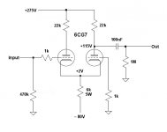
Well, there's one more trick left. If we use a resistor in the LTP tail instead of using the extra triode in the first tube as a CCS, we can use the first tube as a half an LTP, or a grounded-grid amplifier. Basically, you make an LTP, then you take only the non-inverting output and couple that to the following stage. As in the picture attached. That gives you half the gain (like an LTP) but a single-ended output. It is a waste of gain, but will certainly reduce distortion.
Whew, mental gymnastics!
-
Start from the output stage:
- We figure a pair of 6L6's with plate voltage of +300V into your OPTs with 3k6 primaries will bias up at about -17V. So the driver stage needs to put out a push-pull signal of 20V peak (to be safe), on the plus and minus sides.
- In an LTP-phase splitter, the gain is halved (it sees only a single-ended input to one of its inputs, the other is grounded).
The 12AT7 has a mu of about 50 (when plate loaded), so can reach a gain of maybe 25 in the LTP. That means that if we had 1V pk available at the input, a single 12AT7 LTP could drive your 6L6 output stage to full power. (Since a CD player can put out over 2.5V peak, it's safe to say there's even a margin for 6dB of NFB with a 12AT7 LTP.) The first tube socket could then be used for a pentode CCS.
If we use a medium-mu dual triode like a 6CG7, then the gain of that as an LTP will only be around 7. That means we need approx 3V peak input to the LTP to reach our required 20V of drive to the 6L6 grids. Maybe 4V input, just to be safe.
So the 6CG7 Vgk can be as low as 4V. The operating points could be
Va = 155V
Vg = -4V
Ia = 7mA
ra = 8k
Since the B+ is likely to be only +290V, we figure we need to drop 135V with 7mA, so 135V/.007A = 19,300 ohms
20k ohms would be close enough. Maybe 18k if you can't find 20k.
Using the negative supply to feed the tail is now mandatory. If you get -90V, you could use a 6k8 5W resistor instead of using a tube or a solid-state CCS there. Balance would be worse, though.
Now that that is figured out, we see that the gain required from the preceding voltage amp will be extremely small. With a 6CG7 there, with its mu of about 15, we'll only need 267mV pk of input to drive the amp to full power. Even after 6dB of NFB, that's still only 530mV of input for full power. The amp will be unnecessarily sensitive. What to do?
Well, there's one more trick left. If we use a resistor in the LTP tail instead of using the extra triode in the first tube as a CCS, we can use the first tube as a half an LTP, or a grounded-grid amplifier. Basically, you make an LTP, then you take only the non-inverting output and couple that to the following stage. As in the picture attached. That gives you half the gain (like an LTP) but a single-ended output. It is a waste of gain, but will certainly reduce distortion.
Whew, mental gymnastics!
-
Attachments
Hi Ron,
What values do the resistors need to be in the 6DJ8 CCS?
I'd need to know the voltage of the negative supply, and I'd need to know what current the tube will sink.
--
What the heck.
Let's do it")
I'd say, first let's decide if you can live with an amp that gets to full power with a half a volt of input.
What will be playing into this amp? A CD player?
Do you have a preamp with gain that goes before the amp? Because if you do, you'll get to full blast with the volume control at like 9 or 10 o'clock, which is a drag.
Let me know...
--
I would safely say depending on filtering and dropping resistors, between -230 and -260vdc.
Cool!
The beauty of this Ron is that I am just experimenting. I am about 90% complete on the output tube stage including my bias, etc.
I am setting it up so that I can easily reconfigure the drivers with ease, so let's look at it that way.
If we use the 6CG7 for PI and get the CCS where we want it, then I can play around with the other half of the 6DJ8 to figure out what I want to do. I can also, as mentioned earlier add a simple divider to drop the input sensitivity. Granted it is not ideal.
Blair
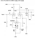
OK, here's the 6CG7 LTP with 1/2 6DJ8 CCS in the tail.
If you decide to change the first stage to a cathode follower, at least you'll have a good (high gm) tube in there for that use. And a negative supply for it too!
--
That cathode-biased CCS circuit came out of Bruce Rozenblit's "Beginner's Guide to Tube Audio Design" (page 39). I double-checked it by reading in Morgan Jones' "Valve Amplifiers" (page 105).
--
Incidentally, those 20k plate resistors for the 6CG7 should be rated 3W, minimum. You might want to get some good quality wirewounds. Not necessary to get non-inductive, but you probably should get something better than the cheap cement coffins.
Attachments
Last edited:
Another thought...
The cathode of the first 6DJ8 will be at about +2V.
The cathode of the second 6DJ8 will be at -93V.
The cathodes of the 6CG7 will be at +4V.
The cathodes of the 6L6's will be at 0V.
We need to reference the heater supplies to something like -40V, so that all the cathodes will be within 50 volts of the heaters. We don't want to exceed the heater-to-cathode voltage ratings.
--
It's the power supply stuff that will get you.
The first stage 6DJ8 is a common-cathode ("single-ended") stage, and so will need a fairly clean B+. You'll want to put an RC filter between the B+ to the 6CG7 and the B+ to the 6DJ8. I'd like to see that 6DJ8 operate with a minimum of 6mA plate current. So...
Ebb = +260V
Ra = 27k
Ea = +100V
Ec = -2.5V
Ia = 6mA
Rk = 430R
ra = about 4k5
gm = 7.5mA/V
(that's from the tube data, not real life)
That 27k plate resistor (Ra) should be rated at 3W, minimum. A 5W wirewound would be better.
The 430R cathode resistor could be replaced by a red LED in series with a 1N4148 switching diode to get the 2.5V from ground up to the cathode.
That leaves us 30V to be dropped from the approx. +290V B+. Each channel should have its own filtered leg off the main supply. If we're dropping 30V with a current draw of 6mA, then...
30V / .006A = 5,000 ohms
5100 ohms will be close enough (5100 x .006A = 30.6)
4700 ohms would also be close enough
That resistor can be a 1/2 watt metal or carbon film (metal preferred), or a 1W metal oxide or carbon film if you want to keep the temperature down.
--
Looking at the CCS supply:
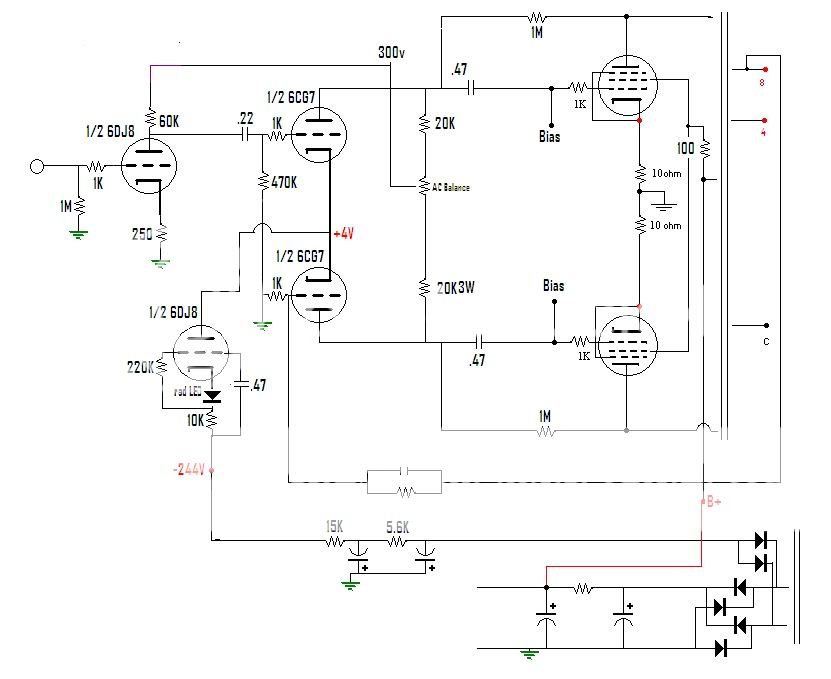
Remember that there will be 14mA of current going through each 6DJ8 CCS, and that's a fair amount of current. You have 21,600 ohms worth of resistance in the negative supply to the CCS's. 21,600 x .028A = 610.4 volts dropped there! That won't work; needs to be re-thought.
If you have -300V available, and you want to get that down to -235V, you take that voltage (-65V to be dropped from the -300V supply) and divide it by the current that will be drawn (2 x 14mA in this case, so 28mA).
65V / .028A = 2,321 ohms
I think each channel should get its own negative supply. You could put a shared CRC first, maybe 100uF-1k-100uF, then each channel could get its own RC "leg" of 2k7-47uF. Each of those resistors should be rated 2W. the caps should be 400V.
1M grid leak resistor from the 6DJ8 grid may need to be reduced in value, but only if necessary.
--
The first stage 6DJ8 is a common-cathode ("single-ended") stage, and so will need a fairly clean B+. You'll want to put an RC filter between the B+ to the 6CG7 and the B+ to the 6DJ8. I'd like to see that 6DJ8 operate with a minimum of 6mA plate current. So...
Ebb = +260V
Ra = 27k
Ea = +100V
Ec = -2.5V
Ia = 6mA
Rk = 430R
ra = about 4k5
gm = 7.5mA/V
(that's from the tube data, not real life)
That 27k plate resistor (Ra) should be rated at 3W, minimum. A 5W wirewound would be better.
The 430R cathode resistor could be replaced by a red LED in series with a 1N4148 switching diode to get the 2.5V from ground up to the cathode.
That leaves us 30V to be dropped from the approx. +290V B+. Each channel should have its own filtered leg off the main supply. If we're dropping 30V with a current draw of 6mA, then...
30V / .006A = 5,000 ohms
5100 ohms will be close enough (5100 x .006A = 30.6)
4700 ohms would also be close enough
That resistor can be a 1/2 watt metal or carbon film (metal preferred), or a 1W metal oxide or carbon film if you want to keep the temperature down.
--
Looking at the CCS supply:
Remember that there will be 14mA of current going through each 6DJ8 CCS, and that's a fair amount of current. You have 21,600 ohms worth of resistance in the negative supply to the CCS's. 21,600 x .028A = 610.4 volts dropped there! That won't work; needs to be re-thought.
If you have -300V available, and you want to get that down to -235V, you take that voltage (-65V to be dropped from the -300V supply) and divide it by the current that will be drawn (2 x 14mA in this case, so 28mA).
65V / .028A = 2,321 ohms
I think each channel should get its own negative supply. You could put a shared CRC first, maybe 100uF-1k-100uF, then each channel could get its own RC "leg" of 2k7-47uF. Each of those resistors should be rated 2W. the caps should be 400V.
1M grid leak resistor from the 6DJ8 grid may need to be reduced in value, but only if necessary.
--
Last edited:
Just in case you haven't started wiring yet...
I wonder if you're beginning to see how cool Eli's El Cheapo design is. It's so simple, yet very clever in getting the job done to a high standard. You could implement El Cheapo with a paralleled 6DJ8 as the CCS for the 12AT7 LTP. I'll bet that hasn't been done yet.
Or we can press on with this design. It's fun too. I'm curious how it turns out.
--
I sim and scope all my PS.
That negative supply is correct? Are you sure?
That 15k resistor alone will drop 210V. That leaves only 38V for the 6DJ8 and its load resistor. That just can't be right. Please explain.
--
Last edited:
That negative supply is correct? Are you sure?
That 15k resistor alone will drop 210V. That leaves only 38V for the 6DJ8 and its load resistor. That just can't be right. Please explain.
--
I used the values from the 6l6 schematic I found. This is more along the lines of something I would trial and error to get my voltages. I thought that 15K looked a bit high too, but he is using a resistor for cathode bias and not a tube, so pulling the 15K all together is the thing to do and just using a single stage CRC.
Blair
- Home
- Amplifiers
- Tubes / Valves
- Bogen RP40A transformers....what to build with them?