I would worry about the negative supply for the current source. At power up there will be no voltage there. Current can't flow through the return diodes from ground to the transformer windings as they are in opposition to the negative supply diodes.
Once everything starts conducting, there will be a current path through the current source, through the LTP and back, however I doubt the minus supply will ever function properly.
Thanks for bringing this up. I'm actually glad to see someone is checking our thinking for mistakes.
Why exactly wouldn't the minus supply function properly, at least once the 6DJ8 is warmed up and conducting?
Would a plain old resistor down there in the LTP tail present the same problems? Small signal diodes could be used between grids and cathodes of 6CG7 to keep the cathodes close to ground potential, and therefore close to the heaters' potential (to keep from exceeding peak heater-to-cathode voltage ratings).
I found that triode current sink described in a couple of well-regarded texts, and I know JC Morrison used it in an amp from the Fi Tube Audio Primer (the PP 807 amp, I believe). So I'm curious where I went wrong with this implementation. Any way you see to save it?
How about a husky damper-diode tube rectifier in series with the B+ to act as a soft-start? (Or a paralleled-plate 5U4 perhaps?)
The idea was to find a way to use up the tube in that extra 9-pin socket. I'm not married to the idea, but it seems to me that it ought to work.
--
Hi Gimp,
That makes sense. I do not have room for another transformer.
As Ron pointed out a while back in the thread, the LM334Z has a current rating of 10mA, so it is not optimal. What about larger devices like the LM317 wired as a current regulator?
As Ron said, it is really a matter of us trying to use all available triodes here, but nothing that is mandatory.
I'd actually prefer to not have to try to fit another supply in here.
Also, is there not a way to use the triode strapped like the example here as the current sink/shunt to ground vs. a negative plate supplied CCS?
The Valve Wizard
Thanks guys!
Blair
I figured the transformer is 225V-0-225V under load. But that's really only a guess.
You can certainly use an LM317 as the CCS for the 6CG7. However, the LM317 has a max voltage rating of 37V, so you would need a much lower negative voltage rail for that. You have that 90VAC winding to work with, right?
However, as many here will be quick to point out, the LM317 is not the best performing device for use as a CCS. Its (desirable) ultra-high impedance degrades as you go up in frequency, starting at about 10kHz. However, it's still probably no worse than a triode would be.
The feature of the LM317 that makes it recommendable is that it is so easy to use. To find the set resistor value for the current you want, you simply take the LM317 reference voltage of 1.25V divided by the current you want. So 1.25V / .014A = 89.29 ohms. 91 ohms would be close enough (rearranging the preceding, 1.25V / 91R = 0.01374A, or 13.74 mA).
A 10M45S or DN2540 depletion mode MOSFET is better for use as a CCS, and better yet would be two of these devices in a cascode. These devices are good for voltages up to 400V, so there's no reason not to use them, except...
The only reason not to use one of these depletion mode MOSFETs is that finding the proper resistor value to set the current you want might be tricky, because like most transistors, these devices characteristics can vary over a wide range. You can use a small multiturn pot to dial in the desired current, but pots are less reliable than fixed resistors. Paralleling resistors to make the correct value can be a bit fiddly, but if you don't mind going through that extra effort, that's the way to do it.
If you start using these devices, you could use one in the plate of the 6DJ8 (as a constant current *source*, instead of a *sink*) and get even better performance from that part of the circuit.
Now you've got some silicone in your tube amp, but it's getting slicker -- if that's the direction you want to go in. And now you've got half a 6DJ8 you're not using.
Again.
--
Last edited:
Hi Ron,
I know this leaves an unused 1/2 6DJ8 per channel, but it does simplify things to an extent.
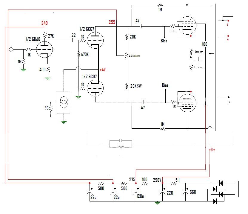
Now for the dumb questions. Why can't I just use the LM317 like the 334Z in this circuit?
http://www.diytube.com/st70/diytube_st70_B.pdf
No neg voltage required?
I found a current regulato calculator for the 317 and 90 ohms gets me 14mA.
LM317 / LM338 / LM350 Voltage and Current Regulator Calculators Just in case you want it.
Am I missing something?
Thanks,
Blair
I know this leaves an unused 1/2 6DJ8 per channel, but it does simplify things to an extent.
Now for the dumb questions. Why can't I just use the LM317 like the 334Z in this circuit?
http://www.diytube.com/st70/diytube_st70_B.pdf
No neg voltage required?
I found a current regulato calculator for the 317 and 90 ohms gets me 14mA.
LM317 / LM338 / LM350 Voltage and Current Regulator Calculators Just in case you want it.
Am I missing something?
Thanks,
Blair
Hi Ron,
I know this leaves an unused 1/2 6DJ8 per channel, but it does simplify things to an extent.
Now for the dumb questions. Why can't I just use the LM317 like the 334Z in this circuit?
http://www.diytube.com/st70/diytube_st70_B.pdf
No neg voltage required?
I found a current regulato calculator for the 317 and 90 ohms gets me 14mA.
LM317 / LM338 / LM350 Voltage and Current Regulator Calculators Just in case you want it.
Am I missing something?
Thanks,
Blair
No, you got it. 91 ohms = 13.74mA, 90 ohms = 13.89mA. No negative voltage required.
91 ohms is an off-the-shelf resistor value, which is why I mentioned it. 90 ohms could be made by paralleling two 180 ohm resistors. Whichever you prefer.
The problem with running the LM317 straight from the 6CG7 cathodes to ground is that the LM317 needs a couple of volts across it to operate. If the 6CG7 is overloaded and is driven close to grid current, the bias would go close to 0V and the LM317 would stop conducting. The distortion would be spectacularly horrible. So I like to see it used with more like +5 or +6V minimum Vgk for the 6CG7's.
Try the LM317 with a set resistor of 91 ohms and see what voltage appears at the 6CG7 cathodes. If it's higher than +4V to ground, then I think it'll be OK. If it's lower, then you should increase the value of Rset to 100 ohms. That will put 6.25mA on each 6CG7 triode (about 12.5mA combined).
--
BTW, that 12AU7 LTP used with an LM334Z in the tail would not be as nice as a 6CG7 with more current going through it. 6CG7 and 12AU7 will bias up just about the same, but 6CG7 has lower distortion to begin with, and getting the current closer to 8mA per triode reduces distortion further. Better sound should result.
--
have a bunch of irf9610s laying around.
That's an enhancement mode MOSFET, no? Not as easy to wire up as a depletion mode MOSFET for use as a CCS, and the DN2540 or 10M45S are not at all expensive. (Like $1.20 ea or so)
--
More for edification than anything else...
RE: Getting positive supply and negative supply from a single secondary...
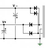
Once in the past, I used a center-tapped secondary with two diodes to form a full wave rectifier for positive voltage and two more diodes in reverse to form a full wave rectifier for negative voltage. This worked fine.
Could two diode bridges be used in a similar fashion? One bridge would have its negative side grounded, producing the positive voltage, while the other bridge would have its positive side grounded, producing the negative voltage.
If it works with a center-tapped transformer secondary, is there a reason why it will not work with two diode bridges, each forming their own "center tap"?
(I always get into trouble in the electro-magnetic world.)
--
RE: Getting positive supply and negative supply from a single secondary...
Once in the past, I used a center-tapped secondary with two diodes to form a full wave rectifier for positive voltage and two more diodes in reverse to form a full wave rectifier for negative voltage. This worked fine.
Could two diode bridges be used in a similar fashion? One bridge would have its negative side grounded, producing the positive voltage, while the other bridge would have its positive side grounded, producing the negative voltage.
If it works with a center-tapped transformer secondary, is there a reason why it will not work with two diode bridges, each forming their own "center tap"?
(I always get into trouble in the electro-magnetic world.)
--
Attachments
I will try the 317 with 90 ohms to ground and let you know what I have on the cathodes. I think it will be OK. I can push the bias up to 8mA per triode if you think that is better?
Blair
90 ohms is fine. Maybe you can leave the 317's wired up so that you can change the set resistors in the future? Just in case you have to diddle with them.
I think that if you put 16mA through the LTP that you won't have a high enough Vgk to get enough voltage swing to the 6L6 grids. If we're pleasantly surprised by a higher than expected Vgk there, we can goose the current a little later. I'm not sure you'd be able to tell by ear the difference between 7.44mA per side and 8mA per side.
--
I'm not sure you'd be able to tell by ear the difference between 7.44mA per side and 8mA per side.
I can tell you this, though... A 6CG7 sounds a heck of a lot better with 7.5mA going through it than with 3 or 4mA going through it. It's a big difference, from my own limited experience. It's worth a little suffering to get the current up past 7mA per side in that LTP.
--
Why will it suffer to get 7-8mA?
No, I'm suffering a little trying to figure out how to squeeze that into the design without breaking something!
")
--
I know. I was looking at that yesterday. It is going to be a tight fit! No esoteric couplers in this build!
Yeah, and that too. (I was thinking about exceeding the current capacity of the power transformer, actually...)
--
- Home
- Amplifiers
- Tubes / Valves
- Bogen RP40A transformers....what to build with them?