I cannot for the life of me find the schematic for this receiver, but have seen the RP40 which is NOT the same. Anyway, I do however assume that the output stage is the same in both because they are part of the same series and the tubes are the same 7355s. I believe the output trannys are 6.6K, but no UL taps. The receiver was spec'd at 20W, so I am unsure if I really want to push it since they are not super beefy.
The interesting thing is that the B+ must have been around 300-325v. I get 234VAC with 120VAC in with no load.
Any suggestions on what to build with these transformers? I'm leaning towards 6L6 PP in triode with a fixed bias. I'm not sure if I can get 20W out of them though.
Any other thoughts to get 15-20w in triode? Any schematics?
Thanks!
Blair
Hi Blair,
You didn't say if the power transformer is 234V-0-234V (468VCT) or if it is 234VAC and 0 (not center-tapped, in other words).
With no load, the voltage will be much higher than fully loaded. I wouldn't be surprised if the loaded voltage would be more like 200VAC. I'll bet that transformer was used with a voltage doubler power supply (a lot of 1960s tube receivers did that). It probably got something like +400VDC, but at only 200mA max current.
6.6k ohm primary is good for a number of different tube types. But with only 200mA available from the power transformer for both channels, your choices are pretty limited.
What about 7591's? You wouldn't get a lot of power, but they'd be really easy to drive cleanly. They're good for 20 watts max dissipation, so if the B+ was 400V, that would be 50mA per tube. That would work, I think...
Eli Duttman's El Cheapo or gingertube's Baby Huey would be great for adapting to 7591's. That would be a worthy project.
There's not much in the triode choices that will run optimally into a 6.6k p-p load that won't need more current and a higher plate voltage. EL84 or 6V6 in triode would work better into something like a 10k load, but max plate voltage is about +325V or so. You'd only get about 5 watts per side from those. 7591 should work well in triode and would be ridiculously easy to drive, so could be run from a very simple driver stage (maybe one tube per channel). I would expect only about 8 watts per channel from triode-wired 7591's.
Wow, this is a challenge. Maybe a pair of 2A3 or 6B4G per side. Those want to see something like a B+ of 300V with a plate current of 50mA (15 watts max dissipation per tube). So the power transformer would be just barely adequate, and only if you use the tubes with cathode bias and maybe a choke input power supply filter. But you could get at least 10 watts per side from that.
Add the current for the driver stage, and 2A3's will need a capable one. Typically that would be three 6SN7 (or 12AU7) type tubes, which need about 48mA of plate current for all of them, and 1.8A of heater current. Can you add a second smaller power transformer for the driver stage?
--
The interesting thing is that the B+ must have been around 300-325v. I get 234VAC with 120VAC in with no load.
You didn't say if the power transformer is 234V-0-234V (468VCT) or if it is 234VAC and 0 (not center-tapped, in other words).
With no load, the voltage will be much higher than fully loaded. I wouldn't be surprised if the loaded voltage would be more like 200VAC. I'll bet that transformer was used with a voltage doubler power supply (a lot of 1960s tube receivers did that). It probably got something like +400VDC, but at only 200mA max current.
6.6k ohm primary is good for a number of different tube types. But with only 200mA available from the power transformer for both channels, your choices are pretty limited.
What about 7591's? You wouldn't get a lot of power, but they'd be really easy to drive cleanly. They're good for 20 watts max dissipation, so if the B+ was 400V, that would be 50mA per tube. That would work, I think...
Eli Duttman's El Cheapo or gingertube's Baby Huey would be great for adapting to 7591's. That would be a worthy project.
Any other thoughts to get 15-20w in triode? Any schematics?
There's not much in the triode choices that will run optimally into a 6.6k p-p load that won't need more current and a higher plate voltage. EL84 or 6V6 in triode would work better into something like a 10k load, but max plate voltage is about +325V or so. You'd only get about 5 watts per side from those. 7591 should work well in triode and would be ridiculously easy to drive, so could be run from a very simple driver stage (maybe one tube per channel). I would expect only about 8 watts per channel from triode-wired 7591's.
Wow, this is a challenge. Maybe a pair of 2A3 or 6B4G per side. Those want to see something like a B+ of 300V with a plate current of 50mA (15 watts max dissipation per tube). So the power transformer would be just barely adequate, and only if you use the tubes with cathode bias and maybe a choke input power supply filter. But you could get at least 10 watts per side from that.
Add the current for the driver stage, and 2A3's will need a capable one. Typically that would be three 6SN7 (or 12AU7) type tubes, which need about 48mA of plate current for all of them, and 1.8A of heater current. Can you add a second smaller power transformer for the driver stage?
--
I'm leaning towards 6L6 PP in triode with a fixed bias. I'm not sure if I can get 20W out of them though.
With 400V at the plates, and 50mA through each 6L6, I'd expect only about 10 watts per channel in class A. You could add a hefty driver like Tubelab's PowerDrive and run them into class AB2.
--
Hi Rongon,
Most of the Bogen stuff did not have a doubler from what I see. He used lower voltage B+ and ran the tubes very conservatively. The RP60, which is similar, ran 335V B+ on the 7355s for 30W. I suspect that using a FWB, you are spot on at around 290-300VDC. I think for simplicity sake, I will use pentode to keep it simple. That should keep me at my 20W or so. I am looking at a schematic by Tim Williams:
http://webpages.charter.net/dawill/tmoranwms/Circuits/Stereo_6L6_PP.gif
Since I already have a fixed bias set up on the top plate, I will convert it and use a different front end to accomodate formy pre drilled chassis🙂
Here are a few shots of what I'm working with.
I'll post in another post


I am looking at a schematic by Tim Williams:
http://webpages.charter.net/dawill/tmoranwms/Circuits/Stereo_6L6_PP.gif
Since I already have a fixed bias set up on the top plate, I will convert it and use a different front end to accomodate formy pre drilled chassis🙂
A 2-stage LTP to PP design. I like it. I built something like that using 6N30P LTP to PP 2A3s, but it needs a preamp with about 10x gain.
Keep us posted on how it turns out. I'm very curious how you end up liking it.
--
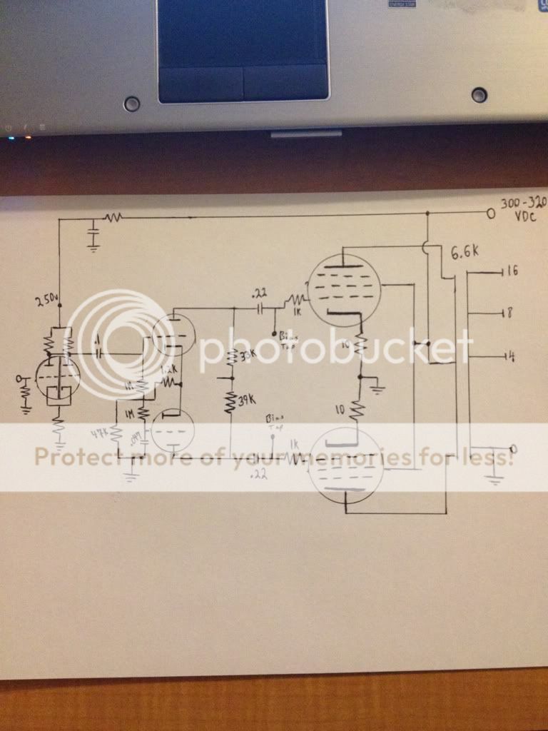
I think I'm going to try something like this.http://i1263.photobucket.com/albums/ii628/blair_4/c5afda31.jpg
The drawing is pretty crude, but you get it.
Blair
In order to get a satisfactory damping factor in full pentode mode, NFB of some kind is mandatory.
Open loop linearity in full pentode mode is better, if g2 B+ is regulated.
Open loop linearity in full pentode mode is better, if g2 B+ is regulated.
Hi Eli,
I know it is much better to have a regulated G2, but I am not sure is I have the space for it. I thought about a choke feeding it from the B+, but again it is a space issue.
NFB is an option, but I'm not sure where/how to tap it into the front end.
Thanks,
Blair
I know it is much better to have a regulated G2, but I am not sure is I have the space for it. I thought about a choke feeding it from the B+, but again it is a space issue.
NFB is an option, but I'm not sure where/how to tap it into the front end.
Thanks,
Blair
A choke decoupling g2 B+ from the main rail is pretty good. Talk to Jim McShane about the g2 B+ choke he installs, when refurbishing a H/K Cit 5. There's little room under that hood too.
Think about using the NFB setup in "El Cheapo". Instead of grounding the non-inverting grid of the LTP, via a cap., use that grid as the point NFB is applied. The CCS in the LTP's tail is essential to force symmetry upon both phases. So, equal value anode load resistors is correct.
Think about using the NFB setup in "El Cheapo". Instead of grounding the non-inverting grid of the LTP, via a cap., use that grid as the point NFB is applied. The CCS in the LTP's tail is essential to force symmetry upon both phases. So, equal value anode load resistors is correct.
Attachments

Hi Eli,
Thanks for the diagram. I found another NFB example where the tap is at the VA stage on the cathode. Either look OK to me.
Looking at the original amp carcass, there is an unusual little cylinder labeled 500 coming off the B+ for the anodes and that feeds the G2 of the power tubes. It appears to be ceramic like a resistor, but mounts with a clamp like a through hole cap.
Is it a resistor?
Blair
Hi Eli,
Looking at the original amp carcass, there is an unusual little cylinder labeled 500 coming off the B+ for the anodes and that feeds the G2 of the power tubes. It appears to be ceramic like a resistor, but mounts with a clamp like a through hole cap.
Is it a resistor?
Blair
Yes, it is very likely a 500 ohm power resistor for the G2's. If you measure it with a multimeter, do you get something like 500 ohms? I've seen resistors like that on old Scott integrated amps and the like.
rongon,
I have data for the RP-40a (original owner's manual with schematics), the RP-40 (SAM's), and the AP-60 (SAM's). If you give me an email I can send you the data you need. Just recently began to evaluate the AP-60 and found the OPT primaries were both bad. Oh well. Guess I'll start on the RP-40a's (I have a complete unit and one without OPT's but which is better cosmetically).
Best,
John
Thanks for the diagram. I found another NFB example where the tap is at the VA stage on the cathode. Either look OK to me.
Count the coupling caps. in the signal path, when you apply the NFB to the voltage gain stage's cathode. IMO, there are too many RC high pass poles present in the signal path, under those circumstances. It's all too easy to satisfy the Barkhausen criteria and end up with a phase shift oscillator, instead of an amp. 🙁 When the short loop to the non-inverting grid of the LTP is employed, it's nearly impossible to get phase shift oscillation. 😉 The schematic provided shows an unbypassed cathode resistor, in the voltage gain setup. The local current NFB, AKA degeneration, inherent in that arrangement takes care of linearizing the stage.
Thanks nerdorama, but I think deicide67 is the one who has the receiver.
10-4. I got an email and sent the manual.
John
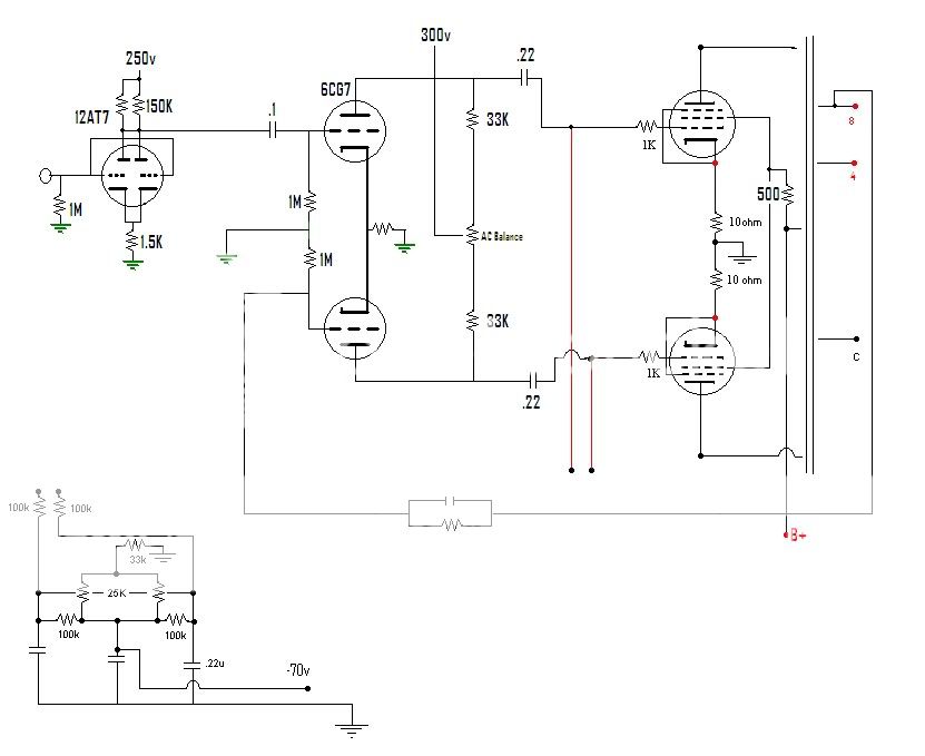
How does this look? I will likely end up using 12AT7 PI and 6DJ8 VA though after digging in my garage🙂
Thanks!
Blair
Thanks!
Blair
How does this look? I will likely end up using 12AT7 PI and 6DJ8 VA though after digging in my garage🙂
Wouldn't that be an awful lot of voltage gain for a pair of 6V6's? Or were you thinking 6L6's?
What about making the first stage a long-tailed-pair phase splitter (like the driver in Eli's El Cheapo) using a 6CG7 (or 12AT7 if you want higher gain), and then the second stage could be a push-pull driver using a tube with a low plate resistance (and low-ish mu)?
Something like the PP 6L6GC AB2 amp... ?
There are simpler versions too, without the MOSFET's, if you only need class A operation.
--
Hi Rongon,
I plan to use 6L6 power tubes.
I found a pair of 6CG7s to use for the PI, but I still plan to use the 6DJ8 if it will swing enough voltage. I have a pair of 6H30s I could use also, but I'd rather save them for a bigger amp that needs the current to drive it.
Do you think the schematic I provided is too much voltage gain for a 6L6?
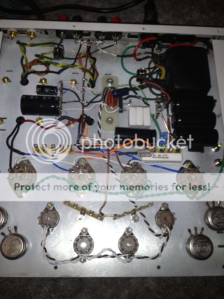
Here is my progress so far. All I lack is the circuit. I'm sitting at 332vdc unloaded, so I am going to assume about a 35-40v drop after installing the tubes leaving me just shy of 300vdc.
Thanks for any assistance!!
I plan to use 6L6 power tubes.
I found a pair of 6CG7s to use for the PI, but I still plan to use the 6DJ8 if it will swing enough voltage. I have a pair of 6H30s I could use also, but I'd rather save them for a bigger amp that needs the current to drive it.
Do you think the schematic I provided is too much voltage gain for a 6L6?
Here is my progress so far. All I lack is the circuit. I'm sitting at 332vdc unloaded, so I am going to assume about a 35-40v drop after installing the tubes leaving me just shy of 300vdc.
Thanks for any assistance!!
- Home
- Amplifiers
- Tubes / Valves
- Bogen RP40A transformers....what to build with them?