Hi Ron,
I suspect my B+ to be 10-20V higher. I was just being conservative on the small tube current to be safe.
4 X 12AU7
1 X 12AT7
6 X 12AX7
3 X 6AU6
2 X 6BA6
1 X 6AB4
2 X EM84
4 X 7355
23 tubes")
If you average 5mA per tube, it is closer to 250mA if the power tubes are biased at 80mA. I think it might be even a little higher. It is the funkiest transformer I have used because it was "dipped" / impregnated with this black rubbery substance. I'm sure it is probably asbestose, and the fact that I sanded it down will kill me. LOL!!
All joking aside, there are plenty of ways to get bias voltage off the B+, or tapping the filament winding that has reserve current and using a small 12v transformer that will tuck away for my -60-75v.
The nigh question will be whether or not the bias winding has the current capacity, and whether or not that 30V is really going to make the "night and day" difference.
I liked you 6DJ8 PI sketch. That tube works well with low voltage.
Supposing we use that and/or the 12BY7A as suggested fro
The HK Citation V, it should work well.
I could also use a SRPP driver and use a 250-280v B+. even the 12AU7 with 220V will give me 16v or so conservatively biased at that B+.
Blair
I suspect my B+ to be 10-20V higher. I was just being conservative on the small tube current to be safe.
4 X 12AU7
1 X 12AT7
6 X 12AX7
3 X 6AU6
2 X 6BA6
1 X 6AB4
2 X EM84
4 X 7355
23 tubes
If you average 5mA per tube, it is closer to 250mA if the power tubes are biased at 80mA. I think it might be even a little higher. It is the funkiest transformer I have used because it was "dipped" / impregnated with this black rubbery substance. I'm sure it is probably asbestose, and the fact that I sanded it down will kill me. LOL!!
All joking aside, there are plenty of ways to get bias voltage off the B+, or tapping the filament winding that has reserve current and using a small 12v transformer that will tuck away for my -60-75v.
The nigh question will be whether or not the bias winding has the current capacity, and whether or not that 30V is really going to make the "night and day" difference.
I liked you 6DJ8 PI sketch. That tube works well with low voltage.
Supposing we use that and/or the 12BY7A as suggested fro
The HK Citation V, it should work well.
I could also use a SRPP driver and use a 250-280v B+. even the 12AU7 with 220V will give me 16v or so conservatively biased at that B+.
Blair
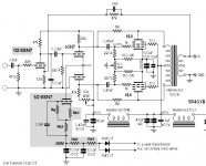
This schematic gets 10W, perfect compliment for my transformer set, and yields low distortion:
http://www.joeltunnah.com/images/6L6amp_schematic.JPG
http://www.joeltunnah.com/poweramp01.html
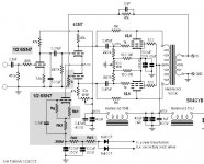
Looks pretty nice, and the 6CG7 can be substituted for the 6SN7.
The 6J5 could be replaced with another pentode for a 9-pin compliment.
Thoughts?
Blair
http://www.joeltunnah.com/images/6L6amp_schematic.JPG
http://www.joeltunnah.com/poweramp01.html
Looks pretty nice, and the 6CG7 can be substituted for the 6SN7.
The 6J5 could be replaced with another pentode for a 9-pin compliment.
Thoughts?
Blair
Why would fixed bias cause harm?
You could use half a 6DJ8 as the common-cathode input stage, and use its second triode as the current sink for your 6CG7 LTP, thus not wasting any tube sections or the negative supply you have. 6DJ8 would be chosen because it will work better with lower plate volts than 6CG7.
Just a(nother) thought.
I like the Schade feedback in there. Nice way to eat up some gain, of which you'll have plenty, for a useful purpose.
--
I'm in. Looks nice. I can use a single pot for the bias voltage and add a balance pot underneath.
That way I can use the second pot on top as the 10K adjustment for the 6CG7 current.
How would it look (schematic) to use the second half of the 6DJ8 as the current sink?
Thanks,
Blair
That way I can use the second pot on top as the 10K adjustment for the 6CG7 current.
How would it look (schematic) to use the second half of the 6DJ8 as the current sink?
Thanks,
Blair
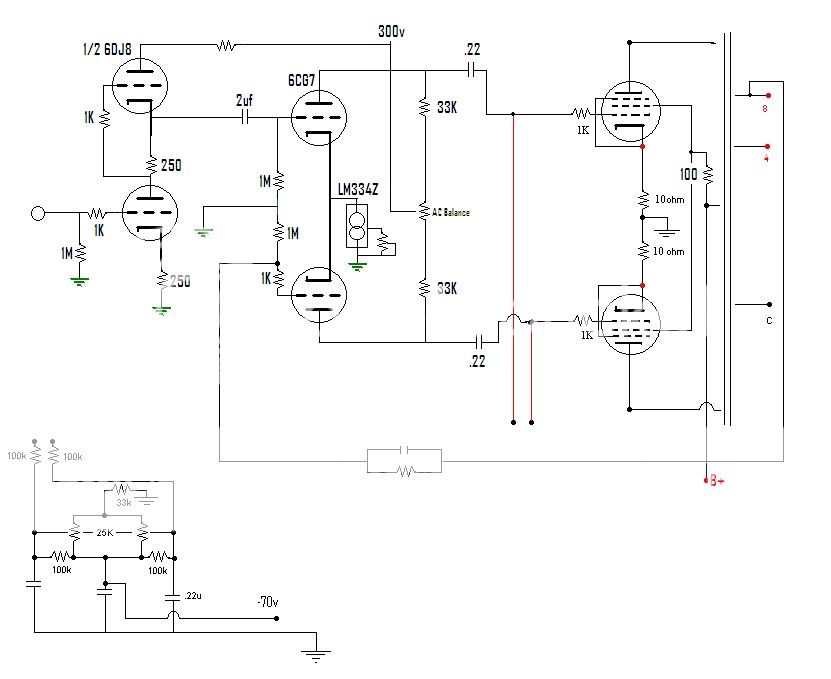
Unlike the usual practice, and because the B+ voltage is so low, the first stage voltage amp is RC coupled to the LTP-phasespliiter-driver stage. That means one more RC coupling to create a time constant and the possibility of one of those RC's forming a resonance.
So, for stability's sake, you might consider moving the NFB so that it is fed to the grounded grid of your LTP-phasespliiter-driver stage, instead of the cathode of the input tube. The more stages you have inside a feedback loop, the more phase inversions and time constants will be inside the feedback loop, and the more likely something will oscillate.
You'll wind up with the first stage having no feedback around it, but that might be a good thing. That's where you have an excess of voltage gain (x12 or so), which could be used to drive the LTP-with-NFB.
Anybody? Bad idea? Good idea?
--
Attachments
Last edited:
I wonder about the 6dj8 in SRPP? On 165v or so, it can deliver 20X gain. Then either use a silicon CCS. I have used the 334Z like in the DIYTUBE ST-70 and Mark III schematic.
I'm not worried about the current per se. There are a ton of amps out there with the 12AX7 up front. That's about as dinky as it gets
Blair
I'm not worried about the current per se. There are a ton of amps out there with the 12AX7 up front. That's about as dinky as it gets
Blair
Sure, something like that. I would do things a little differently, though.
First off, why do you need that 1M resistor from the grid of the 2nd half LTP to ground? The 1k resistor to ground acts as the grid stopper, and conveniently forms the lower half of the voltage divider for the feedback loop. The first half of the LTP probably needs a 1k grid stopper from the junction of the interstage cap and the 1M grid leak resistor going to the 6CG7 grid.
I believe an SRPP in the first stage is unnecessary. Since Vgk of the LTP is going to be around -5V to -6V, the first stage only has to output 5V to 6V peak, plus the extra to compensate for negative feedback, so let's say 12V peak. A common-cathode 6DJ8 can do that from something like 500mV peak input. That is plenty sensitive, too sensitive for CD players, DACs and the like, and gives you lots of room to make back the gain reduction from adding NFB. So I like the idea of using the first triode as a common-cathode voltage amp, and that second triode as a current source, because...
The LM334Z is limited to 10mA max. That's only 5mA per 6CG7 triode. 6CG7 begins to achieve its best linearity starting at 7 or 8mA per triode. So you'd be running your 6CG7 in that sort of "dry" or "thin" sounding region where its plate resistance is going high. Having a negative supply feed the LTP tail and using a more robust device as a CCS allows you to use more current there. Since that device and a negative supply are sitting there waiting for you, why not use them to get higher performance?
--
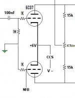
OK, I've attached a picture of the LTP as I see it.
Changes are:
- The way the grids are connected to ground and to the NFB loop.
- Input cap can be much smaller if you use a 1M grid leak resistor. .01uF to .022uF is plenty to reach a -3dB down point well below 10Hz.
- 6CG7 should have 7mA per triode plate current. Given your +300V B+ limit, that means the plate resistors must be much smaller value; 15k in this version, and the CCS needs to be able to deliver 14mA per 6CG7. Or you could use the 6CG7 with lower current, as you proposed, and see if you like it. It might be just fine.
- You wouldn't happen to have any 12BH7 hanging around, would you? That would get you out of this scrape.
--
Attachments
Last edited:
- Home
- Amplifiers
- Tubes / Valves
- Bogen RP40A transformers....what to build with them?