You may want to recheck that amp impedance. I though my ICEPower at 10k was low...
I don't think there is a tube in 2nd socket, or a paralleled tube that will get you 2 - 10 ohms.
EDIT:
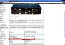
I googled it and it says 100k unbalanced input impedance, not 10. The aikido will have issues driving it at 100k.
....there must be a way to do it....surely....
3 paralleled 6c33c per channel will get you to around 6 ohms. With the 6,3V heater.... That's 20A of heater power per channel. 40A stereo....there must be a way to do it....surely....
What is the benefit of modifying/building/designing a pre to have a 2 - 10 ohm output impedance specifically for an amp that has 100K input impedance?
6C33 - IIRC, that is the tube everyone always raves about for a Cyclotron Output-transformer-less amp - low voltage high current, correct?
6C33 - IIRC, that is the tube everyone always raves about for a Cyclotron Output-transformer-less amp - low voltage high current, correct?
Last edited:
Did some readings last night:
B+ to G = 230VDC
G to H+ = 65V
G to H- +53v
B+ to H+ =150v
B+ to H- = 162V
Across R17(1.5K ohm) 322v to 232v
These two Caps are to never exceed 150V
c6 = 173v
Across R5, Voltage should read significantly lower on one side:
Reads 231vac
C21 = 228
C8 = 319
c11 = 229
C22 = 95
C12 = 97, not exceed 160v
the heater voltage works fine. Using the Voltage doubler and get 12.6v all the way to the C25.
Should I increase the B+ to 300V? I guess lowering the value of R17 should get me there?
What is the benefit of modifying/building/designing a pre to have a 2 - 10 ohm output impedance specifically for an amp that has 100K input impedance?
6C33 - IIRC, that is the tube everyone always raves about for a Cyclotron Output-transformer-less amp - low voltage high current, correct?
Its not 100K: but 1K input impedance...!
???
Hmmm, my eyes are failing me, as I see 100k on the amp specs...the Aikido will have NO issues driving this amp as designed with 100k input impedance.
Unless you modified the stock amp to have a 1k input impedance, but why would you do that?
Its not 100K: but 1K input impedance...!
Hmmm, my eyes are failing me, as I see 100k on the amp specs...the Aikido will have NO issues driving this amp as designed with 100k input impedance.
Unless you modified the stock amp to have a 1k input impedance, but why would you do that?
Attachments
Last edited:
check the heater capacitors that they are the right value...I had the exact same problem and since it was the kit and the bag was labeled correctly I just soldered them in...One of the 10,000 uf ones was actually a 450V 47uF that looked identical...threw the heater voltage all off and the tubes were not conducting properly...
lol. just double checked everything on the pad and sure enough. The R17 bag was labeled 1.5k and its actually a 3k resistor, which should explain why there is a 90 Volt drop across the resistor instead of a 45-50v drop.
Last edited:
lol. just double checked everything on the pad and sure enough. The R17 bag was labeled 1.5k and its actually a 3k resistor, which should explain why there is a 90 Volt drop across the resistor instead of a 45-50v drop.
HA HA!!! Yes, after that I double check all values from Broskie's kits...I can see how it happens and surprised it doesnt happen more often...
Must be ones packed late at night and after a couple brews....
HA HA!!! Yes, after that I double check all values from Broskie's kits...I can see how it happens and surprised it doesnt happen more often...
Must be ones packed late at night and after a couple brews....
Long live Late nights and Cold BREWS!!

I guess I'll order some kiwame resistors from Parts Connexion. might as well order replacement for R15, R16, R17, R19 since they are sonically important..
Hi,
I finished my build and all is good except for the low frequencies. Everything is sounding good but there's a serious lack of bass. My first guess is the output caps. I have 0.47uf caps in the C1 position. Maybe these a too small?
What numbers do I need to calculate the value the coupling caps should be?
I read that you need the load input impedance but i'm not exactly sure what this is/how to measure.
Can somebody shine some light on this?
tnx
edit: i'm feeding a rega mira power amp and the manual says: Power amplifier input sensitivity = 818mV. load 24KΩ
Last edited:
What does your build look like. What tubes did you use? Did you use tubecad's pcbs? What schematic did you use? What power supply. Your C1's value is fine.I finished my build and all is good except for the low frequencies.
I use the dual mono octal boards with the janus regulator from tubecad.
6sn7 tubes in all positions.
I just soldered a 2.2uf cap I found in parallel with the 0.47uf caps and bass is much much better. But now, the amp is very sensitive to vibrations. When I knock on the amp, I hear it loudly through the speaker, something I haven't noticed before. I read this can happen when there's too much capacitance in the output caps?
Any thoughts on caps or other parts I should check?
thanks
Last edited:
2 6SN7's in the aikido will yield only about a gain of 9. That is rather anemic depending on what you are driving with it.
I am driving a MOSFET driver stage (Moskido) with an octal aikido 6SL7 input and 6SN7 output. It may be more gain than you want but personally I would rather have the headroom and not need it.
I am driving a MOSFET driver stage (Moskido) with an octal aikido 6SL7 input and 6SN7 output. It may be more gain than you want but personally I would rather have the headroom and not need it.
I use the dual mono octal boards with the janus regulator from tubecad.
6sn7 tubes in all positions.
I just soldered a 2.2uf cap I found in parallel with the 0.47uf caps and bass is much much better. But now, the amp is very sensitive to vibrations. When I knock on the amp, I hear it loudly through the speaker, something I haven't noticed before. I read this can happen when there's too much capacitance in the output caps?
Any thoughts on caps or other parts I should check?
thanks
read this.
tube dampers
8 x 6N8S 6CC10 6SN7 tubes Military FOTON NOS 1960s items in Retail tubes store store on eBay!
ebay store with tubes, expect to wait a month though.
ebay store with tubes, expect to wait a month though.
Hmmm, my eyes are failing me, as I see 100k on the amp specs...the Aikido will have NO issues driving this amp as designed with 100k input impedance.
Unless you modified the stock amp to have a 1k input impedance, but why would you do that?
....you are looking at the 'Type II'...., which does have 100K unbalanced, .....however, .... mine is the 'Type I'..., which has 1K unbalanced. How do I know? I was directly informed by the designer himself.
")
- Home
- Amplifiers
- Tubes / Valves
- Building a Aikido preamplifier