LikeI might try and reference 1/4 b+ with that center tap
")
It's little bit OT, but it is still about Broskie circuit & I don't know where else to ask.
I'm a tube newbie and plan to build Broskie Cathode Follower (BCF) for my very first tube build as it is simple. Everything is clear except about the connection of tube's pin no 9 as I saw contradictory statement on Broskie's user guides.
On BCF user guide : "Capacitors C5 used only with tubes that hold an internal shield at pin 9, such as the 6DJ8 and some 6CG7s" So pin no 9 connected to ground via a capacitor for tube with shield.
But on Aikido user guide : "If the triode’s pin 9 attaches to an internal shield, as it does with the 6CG7 and 6DJ8, then capacitors, C11 and C12 can be replaced with a jumper, which will ground the shield. However, using the capacitors will also ground the shield (in AC terms) and allow using triodes whose pin-9 attaches to the center tap of its heater, such as the 12AU7". So tube with shield : pin 9 direct to ground. For 12xx7, to ground via caps.
I'm confuse, which one is the correct connection for pin 9.
Tubes 6CG7/6DJ8 and other tubes with shield=Either to ground directly or to ground via capacitor. Both methods are fine.But on Aikido user guide : "If the triode’s pin 9 attaches to an internal shield, as it does with the 6CG7 and 6DJ8, then capacitors, C11 and C12 can be replaced with a jumper, which will ground the shield. However, using the capacitors will also ground the shield (in AC terms) and allow using triodes whose pin-9 attaches to the center tap of its heater, such as the 12AU7". So tube with shield : pin 9 direct to ground. For 12xx7, to ground via caps.
Tubes with center tap of heater such as 12AU7=Capacitor only or no connection to anything.
Last edited:
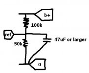
See attached drawing.
So Ref would be the CT? ... B+ and Ground are used...Two resistors in series and ct connected in between?
Yes. Connect Ref to CT of heater transformer.So Ref would be the CT?
Exactly.Two resistors in series and ct connected in between?
See attached drawing.
I hope that is an electrolytic Cap? I have a 47uf 450v in my bin..
Hi!
I have built some tube amplifiers, so now I want to build a preamplifier!
Preamplifier and linestage is the same thing, right?
This is what I am looking for:
*Low Distortion
*Low output impedance
Then I read about the Aikido
Hi
...do you know what the actual output impedance is??? I need an output impedance of <10 ohms....
That depends on the 2nd tube. You could parallel that last tube to get such a low output impedance. Maybe 2 6C33C's per channel.do you know what the actual output impedance is???
Last edited:
...yeah, I need it 'at least' 10ohms..., 2ohms would be ideal....
...so, parallel..., ie: instead of the one tube being in its designated place, you put a 2nd one in parallel to it, (like 2 caps to get a greater capacitance) which reduces the impedence by...half?...each time???
...transformer output stage???...adding an extra transformer??
...so, parallel..., ie: instead of the one tube being in its designated place, you put a 2nd one in parallel to it, (like 2 caps to get a greater capacitance) which reduces the impedence by...half?...each time???
...transformer output stage???...adding an extra transformer??
quote:
Hi
...do you know what the actual output impedance is??? I need an output impedance of <10 ohms....
What are you dring with an impedance of < 10 ohms?
I want to drive an ME 550 Type I SS amp with the Aikido (or other) valve preamp, and the ME has an input unbalanced impedance of 1K ohm, so, taking the ideal ratio of 100/1, adds up to a max of 10ohms...
The ME SS pre-amp, only has an output impedance of 2ohms, so that is why 2 ohms would be ideal/best, but <10ohms is good still...
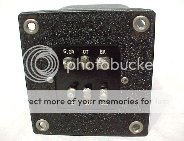
check the heater capacitors that they are the right value...I had the exact same problem and since it was the kit and the bad was labeled correctly I just soldered them in...One of the 10,000 uf ones was actually a 450V 47uF that looked identical...threw the heater voltage all off and the tubes were not conducting properly...
I want to drive an ME 550 Type I SS amp with the Aikido (or other) valve preamp, and the ME has an input unbalanced impedance of 1K ohm, so, taking the ideal ratio of 100/1, adds up to a max of 10ohms...
You may want to recheck that amp impedance. I though my ICEPower at 10k was low...
I don't think there is a tube in 2nd socket, or a paralleled tube that will get you 2 - 10 ohms.
EDIT:
I googled it and it says 100k unbalanced input impedance, not 10. The aikido will have issues driving it at 100k.
Last edited:
check the heater capacitors that they are the right value...I had the exact same problem and since it was the kit and the bad was labeled correctly I just soldered them in...One of the 10,000 uf ones was actually a 450V 47uF that looked identical...threw the heater voltage all off and the tubes were not conducting properly...
All my Capacitors are right. I'm going ot have to double check everything.
- Home
- Amplifiers
- Tubes / Valves
- Building a Aikido preamplifier