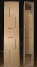
Not glued but still standing!
I have logged 33 hours in the shop so far... All the joinery is cut and everything fits together as it should. I am relieved this part is done, and no "major" mistakes were made. All these joints where made using a table saw, jig saw, handheld drill and file. I do not have a router yet, besides that does not cut "squares" either. A Mortiser would be nice if one can afford all the different chisel bits you need for it (on the list for my dream shop). This definately is pushing my abilities to the max, but that is what diy is all about! All and all I am happy with the reaults so far. Just be warned that if you choose to build a cabinet this way, there is an incredible time commitment involved which is always more then you expect!
Now I have:
The back curves to cut
The driver hole with chamfer
The horn triangles
The back chamber blocks
I am debating whether to finish the inside of the horn before glueing (masking off areas to be glued), as that will make excess glue easier to remove for final finishing. Gluing is always messy and it goes where you do not want it to. I am a strong believer in using too much glue -vs- not enough. Most projects I can clean excess glue off while it is still wet, but with this project, there are a lot of spots that are hard to reach! I also find the inside corners can be very hard to sand "with" the grain. So...
Hang in there guys, I really feel this is all going to be worth it!
Attachments
Overkill!
I know all too well the fallacy of this kind of thinking. By God's Grace I still have an awsome relationship with my 11 year old daughter who's mum and dad (me) where not strong enough to work it out... These days I strive more to give out my personal best. And many of you know that is what it takes for a successful marriage, God bless ya!
Okay, enough of
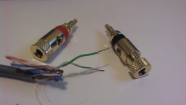
So, it would seem that I went over board on my binding posts and under-rated my transformer for my GC. I have been reading some of the PSU threads in the GC section and it would appear that my 160 VA transformer would be good for one channel, maybe unrated for peaks for both channels. So I may go completely dual mono, with a second 160 VA transformer for the other channel. I went with the 160 VA, becuase it had the 22 volt secondaries I was after. I may need to start a separate thread for this... Of course all that could be a masculine thing too!?!
I am glad you guys are beyond that!
Allen
Isn't that the typical masculine thing? Mine is bigger than yours...
dave
I know all too well the fallacy of this kind of thinking. By God's Grace I still have an awsome relationship with my 11 year old daughter who's mum and dad (me) where not strong enough to work it out... These days I strive more to give out my personal best. And many of you know that is what it takes for a successful marriage, God bless ya!
Okay, enough of
So, it would seem that I went over board on my binding posts and under-rated my transformer for my GC. I have been reading some of the PSU threads in the GC section and it would appear that my 160 VA transformer would be good for one channel, maybe unrated for peaks for both channels. So I may go completely dual mono, with a second 160 VA transformer for the other channel. I went with the 160 VA, becuase it had the 22 volt secondaries I was after. I may need to start a separate thread for this... Of course all that could be a masculine thing too!?!
I am glad you guys are beyond that!
Allen
Attachments
I have logged 33 hours in the shop so far... All the joinery is cut and everything fits together as it should. I am relieved this part is done, and no "major" mistakes were made.
Now I have:
Hang in there guys, I really feel this is all going to be worth it!
Looks impressive, keep them coming.
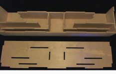
Busy, Busy, Busy
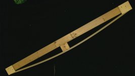
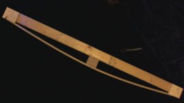
I have been doing overtime at work, a rare blessing. The downside is I have had very little shop time. I got the "bow" jig adjusted right now, so the bow is actually congruent with-in a 1/32" on each side. The first one I built was off 5/16" (first photo). This was due to using two pieces of "cheap" plywood for the bow (spliced in the middle). Also, the center block and outside guides where 1/16 out of square! It does not pay to use lower grade scraps for a jig as curved as this one. The final version (second photo) uses a cut off of baltic birch (one continueous piece) and I used better scraps that where actually square...
...So I have all the cabinet parts labeled to go back together in their current aligned arrangement. Now I am finally ready to cut the bows.
An hour here and an hour there...
...I really wish I had more time to work on this. Golly, if I could figure out a way to build something like this for my overtime pay, then we would really have something!
Namaste, Allen
Attachments
I understand there is a new iron supplement/viagra pill on the market.
Lots of raw, dark, leafy green vegtables is the way to go there and you will not need the help of magnetic pull!
God Bless ya!
Allen
piece by piece
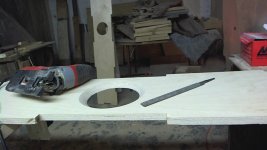
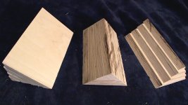
We are getting there guys, one slow step at a time. I got the back curves cut and finished all the same. I did this by clamping all the boards together and filing them all to the same profile and sanding them. This could be done with a belt sander too, if you have one (I do not). I got the driver cutouts started also. I did the chamfers with a jig saw at 45 degree tilt. This is not the most accurate way to do this, so cut inside your lines. I used a course file to get the chamfers more consistent. They turned out well considering I did them this way. These need to be sanded and notched before they are done...
...I am hoping for more shop time this week, still lots of work, but less of life's extras...
Thank for your patience, it is driving me nuts too!
Attachments
Awesome work. I envy your skills and patience.
This will be a build you will be proud of.
Easy with that stuff when installing the drivers. Don't want any accidents")
This will be a build you will be proud of.
The only know side effect is the tendency to point to magnetic north when aroused.
Easy with that stuff when installing the drivers. Don't want any accidents
Last edited:
Allen,
Looking really good and excellent advice from Quadtech on being careful. The A12 are big and beautiful drivers, and the aluminum cones are delicate; quite a few forum members have punctured/creased their Alpairs by mistake.
DIY projects have no deadline. It's taken me a looooong time to my builds also, and I had the help of a carpenter. No hurry - good things comes to those who wait!
The chamfer inside the drivers look ok - make sure your driver screws have good purchase in the plywood. And yes, sanding wil take care of the rough edeges.
Look forward to updates as progres happens.
-Zia
Looking really good and excellent advice from Quadtech on being careful. The A12 are big and beautiful drivers, and the aluminum cones are delicate; quite a few forum members have punctured/creased their Alpairs by mistake.
DIY projects have no deadline
. It's taken me a looooong time to my builds also, and I had the help of a carpenter. No hurry - good things comes to those who wait!The chamfer inside the drivers look ok - make sure your driver screws have good purchase in the plywood. And yes, sanding wil take care of the rough edeges.
Look forward to updates as progres happens.
-Zia
Last edited:
final driver cutouts
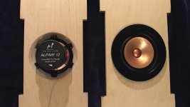
The driver cutouts are done. This is one of those milestones on this project that gives a great sense of peace! There was a lot of trail and adjustment to get the alignment right on these notches. I went this route becuase: #1 - I wanted the chamfer to start right on the inside edge of the bezel and #2 - I wanted to give the screws some wood thickness to grap onto. All and all a successful result, and the drivers are still in tack - whew! In fact the drivers are safe back in their boxes, they only come out to play when it is absolutely necessary!
Next up are the four horn triangles...
Attachments
Awesome work. I envy your skills and patience.
This will be a build you will be proud of.
Thanks quadtech and Zia. It is nice to have a project like this where I can use my skills and "patience". It is not an encouraged gift in the microwave, ADD, instant messaging, pill popping job world!
Easy with that stuff when installing the drivers. Don't want any accidents
That is why I eat lots of fruits and vegetables: good, pure, clean, wholesome vitality! no "accidental" side-effects.
The driver cutouts are done.
You aren't going to rebate them? Do you have another sceme to to get the fronts flush?
dave
Quote:
Originally Posted by ArtsyAllen View Post
The driver cutouts are done.
You aren't going to rebate them? Do you have another scheme to to get the fronts flush?
dave
Exactly my thought's Dave.
You aren't going to rebate them? Do you have another sceme to to get the fronts flush?
dave
Yes, adding solid maple to the fronts and sides. The front and sides are actually going to be curved when all is done. I am doing this by cutting maple into various strips and angles to make a smooth curve. I have not decided on a pattern yet. My goal is to get the cabinets glued, Chip Amps done, and drivers installed for break in so I can choose my pattern. The plain birch cabinets look like to big blank canvases to me! Here I have put so much work into getting the joinery to look good, and I may be covering it all up! That is why I am taking really good pictures, becuase this fuctional astetic may interest other builders. In my mind, the joinery's main purpose is for strength and alignment. So...
...Yes, before you ask, I am crazy, but that is what it takes when building a piece of art!
Thanks for questioning this, it is good to know that you guys are covering my back!
Attachments
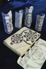
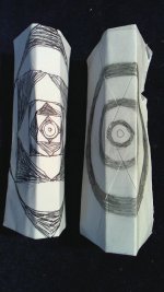
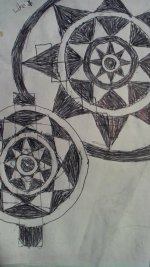
outside designs
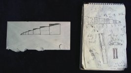
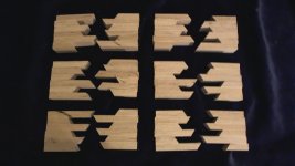
Not sure if I am going with any of these designs, it really depends on how the plain cabinets look with the drivers installed. In the drawings, the white areas are regular grain. The black areas are "end" grain. I have found that using normal grain and end grain together you end up with a dynamic that is similiar to using two diferent kinds of wood. So the finished cabinets will not be as contrasty as these pictures show.
Dave, in the second photo, the drawing on the right was inspired by your EnAbled drivers. If I do this design, I would like to put the EnAbled pattern inside the circles. I like the simplicity of this design.
I like the Sunstar pattern also (thrid photo, right drawing), but not sure if it would be a bit much!
If there is any particular design the inspires any of you, put your votes in!
You do not think I am over doing it a little do ya!?!
Attachments
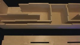
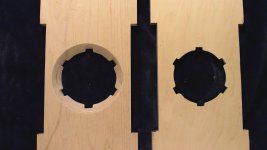
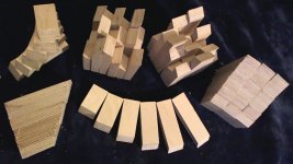
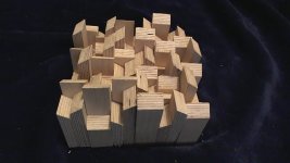
I got the horn exit triangles cut and the back chamber diffusion blocks cut. As you can see, I am filling the voids in with birch on the triangles, instead of sand. Less mess.
I am looking forward to figuring out how I am going to install the diffusion blocks. There are a lot of possibilities. I am quite geeked out by them, they are really cool! Play time!
God Bless
Allen
I am looking forward to figuring out how I am going to install the diffusion blocks. There are a lot of possibilities. I am quite geeked out by them, they are really cool! Play time!
God Bless
Allen
Attachments
artsy indeed
I am just getting started!
Attachments

- Status
- This old topic is closed. If you want to reopen this topic, contact a moderator using the "Report Post" button.
- Home
- Loudspeakers
- Full Range
- Mikasa, next?